I have a small bag of those little trimmer pots. Ill try this.Have a look at the 10mm RF/IF transformers. The ones with the skinny slug. Do any of them show a peak with the slug dead-flush with the rim of the hole?
If so, this is not a resonant peak. It's the inductor's end-of-travel point. That flush position is the coils max inductance setting. It's common for the internal tubular ceramic capacitor to go open circuit. When it does, increasing the inductance will compensate, but not enough to resonate properly.
If the coil's frequency is high enough, soldering a trimmer cap on the solder side of the pcb to the two pins on the resonant side of the coil can fix this without replacing the whole part. Besides, some of the 10mm coils have become hard to find.
This Cobra 142 had a bad case, but the seven trimmer caps restored each tuning slug to resonate well below the max setting and got the radio back to full signal levels.
And if all of them show a proper resonant peak with the slug well below the rim of the hole, this won't help.
73

You are using an out of date browser. It may not display this or other websites correctly.
You should upgrade or use an alternative browser.
You should upgrade or use an alternative browser.
-
You can now help support WorldwideDX when you shop on Amazon at no additional cost to you! Simply follow this Shop on Amazon link first and a portion of any purchase is sent to WorldwideDX to help with site costs.
-
A Winner has been chosen for the 2026 July 4th Retevis RA89R Giveaway! Click Here to see who won!
Trc 458 no receive and carrier on ssb
- Thread starter k9fon12374
- Start date
Ill give that a shot.Hey K9FON -
A question about the "no receive" problem. Is there no receive in both AM and SSB ?? You said you have receive with loud stations. I would check the receive protection diodes (D64/65) . These are on the solder side of the board and were added as a fix post-production. 1N914 diodes. The only 858SSb schematic they are shown on is the TRC-449. If one or the other is shorted, you will have the receive situation you posted. Also check the uPC1156H audio chip. One of the first things to go out when the rig is hooked up backwards. Chip is NLA, but available on Ebay.
As far as the carrier on SSb, have you checked the carrier balance adjustment VR4 ?? It is used to null out any carrier from the balanced modulator. If VR4 has no effect, check to see if it's open. If it's OK suspect that the balanced modulator chip (IC2-MC1495A) is fried
If this doesn't fix things, let us know.
73.
- J.J. 399
Good advice. You won't find anyone here with more experience with the 1978 Uniden SSB CB radios than Jim. He's worth listening to.check the receive protection diodes (D64/65) .
73

People always make fun of something that they don't understand.No attitude but i see why people on facebook make fun of this site.
- J.J. 399
I don't know why folks are so vague in their post and get aggravated because we don't auto-magically know their skill level, what they know, what they don't know, what equipment they have, what they have tried or even their favorite flavor of ice cream. Give me a break.
Defpom got so tired of the "my radio won't transmit" posts on his forum he installed a questionare to cover all the routine things to check first. Don't think it helped all that much, but I'll give him credit for trying.
73
73
@k9fon12374
If I add my real 2¢ .............. I'll get in trouble.
But what I will say is that the SERVICE MANUAL for any of the 858 SSB radios will give you all the answers you want and need ........ your problem is that you have to put in the work to fix it.
It's apparent that you couldn't get your answers from book ........... and that's all you should have said.
73
If I add my real 2¢ .............. I'll get in trouble.
But what I will say is that the SERVICE MANUAL for any of the 858 SSB radios will give you all the answers you want and need ........ your problem is that you have to put in the work to fix it.
It's apparent that you couldn't get your answers from
book ........... and that's all you should have said.73
I have a small bag of those little trimmer pots. Ill try this.
Receive only on HOT signals? On the surface it would seem like the RF/IF section is working... albeit at low gain. Some things you might check (may sound odd)... AGC and Noise Blanker. They both serve to control gain in the RF/IF strip. AGC does it normally to create an even level for varying signal strengths. NB blanker does it instantaneously to remove noise impulses. But either one ... in failure mode could dramatically reduce the gain.
Feed your RF generator in and scope around the AGC bus.... step the incoming RF way up and then way down and see if the AGC bus raises and lowers to track the change in the incoming RF.
As far as the noise blanker .... there will often be a transistor shunted from the IF to ground..... or sometimes.... like a pass element that the IF must get through. If you can find those transistors.... check them out to make sure THEY are not killing the IF. If a shunt transistor.... check for shorted or leak. If a series type... make sure it is not open.
Other than that..... feed the RF generator in at a relatively low input level and scope through the RF amp and the IF amp and mixers and just look for a spot where the gain is lower than you would think and "nose around" that spot.
As far as having a carrier on SSB.... IC2 is your balanced modulator. I would do some scoping around there. It should be getting in RF and AUDIO and putting out double sideband carrier suppressed signal.... so the carrier should be getting nulled out right there in IC2. If it isn't.... either the IC isn't happy with some inputs.... or it has given up the ghost. Again some scoping should help you figure this out.
A frequency counter in line with the coax would reveal if his carrier is coming from the balanced modulator, or if a different fault is making the final oscillate. If so, the frequency on the counter will be nowhere near the selected channel, and won't be all that stable. First question about a rogue carrier in sideband transmit is where is it coming from.IC2 is your balanced modulator.
If the carrier crystal for that mode is badly drifted or tweaked way off, this can aggravate poor carrier suppression on sideband transmit.
73
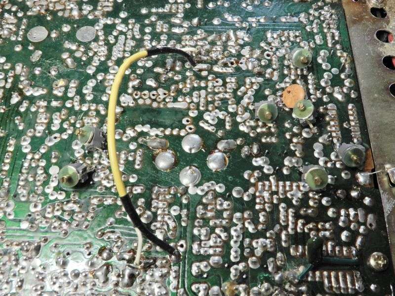
If we know it was hooked up backwards, why not start where the power comes in? Assume D54, C107 and C97 are junk (circled in red), replace them.

The zeners circled in yellow would be forward biased and, with the current limiting of the resistors R161, R113 and R112, they should have protected everything after the blue nodes (assuming they held up). The bottom zener would be the most likely to go having over a quarter watt through it. Make sure those diodes are good.
After that, there are two directions to go (assuming nobody pressed PTT when it was connected backwards). Either a zener will be toast and we need to go through everything on its blue node, and/or something connected to the main rail (black square #1).
There are a few things connected to the main rail, but in my opinion, the only one that stands out to me is the audio IC.
As for the protection diodes, the symptom of low RX matches, but they are isolated from DC, so reverse polarity wouldn't do that. Something else could have.
Lots of resistors around the BM to limit current if things did go backwards there, not sure if 48mA could kill it. The adjustment pot could have simply worn out.
I hope nobody pressed PTT when it was connected backwards because that opens up all sorts of problems, like the diode on the TX relay and the TX regulator (TR24 and its zener), but this post is long enough. I just wanted to go over the first places I would check in that situation.
edit: to shorten post and change red circle as I accidentally circled C106 instead of C107.
Last edited:
That is an excellent thought. I hadn't considered any kind of unwanted oscillation but you are absolutely correct!!!! Much appreciate the additional input.A frequency counter in line with the coax would reveal if his carrier is coming from the balanced modulator, or if a different fault is making the final oscillate. If so, the frequency on the counter will be nowhere near the selected channel, and won't be all that stable. First question about a rogue carrier in sideband transmit is where is it coming from.
If the carrier crystal for that mode is badly drifted or tweaked way off, this can aggravate poor carrier suppression on sideband transmit.
73
dxChat
- No one is chatting at the moment.