Circular polarization can be beneficial in any case where the signal polarity between stations cannot be held stable and the polarization will be expected to change. This happens anytime a signal is reflected back to the other station rather than direct wave line of sight propagation. Examples include satellite communication, moonbounce, VHF and UHF signals experiencing multipath reflections off buildings or terrain and all skywave DX signals reflecting off the ionosphere.
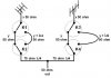
I've used CP for working DX and it can be very helpful and difficult to construct properly. Some of the key construction points are using sets of elements that are as symmetrical as possible. Any imbalance between driven elements will skew the pattern and prevent the CP pattern from forming. The same is true if the phasing harness feeding the driven elements does not provide an exact 90 degree phase delay between the two. The result will be "elliptical polarization"
The idea that "you can't keep a CP antenna in the air very long on this band" is not true. Tens of thousands of "CP ready antennas" have been in the air for decades. Any dual polarity antenna from a PDL-II to the Laser 500 is all that needs to be in the air to make CP. It's how you connect the two feedlines together that determines the difference between CP or VP and HP.
Some people may not realize how often a DX signal will shift polarity on the receiving end. Depending on conditions this can happens dozens of time per minuet. The majority of signal fluctuation we see during DX conditions is not because the path between the two stations has improved or deteriorated, it's because the signal polarity is rotating in and out of a polarization that matches your antenna!
When the polarization is completely mismatched, the signal can easily be attenuated by 20 db. That's the difference from being full copy in DX when the polarization matches, to being lost in the pileup 10 seconds later when the polarity shifts. The advantage CP offers is keeping your station in ALL polarities at one time to prevent this signal loss due to polarization changes resulting from the signal being reflected.
The bad news is this advantage will also cost you 50% of your output power to create. Since you are driving two elements, the total output power will be split between them. That will cost you 3 db whenever the polarization matches the physical orientation of one of the sets of elements on your antenna. In other words if you are talking to a completely vertical of horizontal station, you will be 3 db lower using CP.