• You can now help support WorldwideDX when you shop on Amazon at no additional cost to you! Simply follow this Shop on Amazon link first and a portion of any purchase is sent to WorldwideDX to help with site costs.
  • The Winners of the three Retevis radios 16 Anniversary giveaway are announced!! Click Here to find out if you won!

Uniden grant xl echo board removal

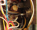
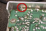
The two wires passing between the RF output and its ground return might couple some RF into a sensitive area.
I would get the wires out from under there and move all wires as far from the RF output as they can be.. Those wires are also sitting right on a coil. Probably not the cause of the talkback though.
1793495976334.png
 
Last edited:
  • Like
Reactions: MKwrench
That is exactly what’s happening here, if I unplug the mic with an antenna connected I still get receive even with the volume turned down fairly low. As an experiment I tried that with my other two 148 gtls and I have to turn the volume all the way up. To hear even a little bit of static coming out of the speaker. The only problem is I don’t see any obvious resistor going from the barrel of external speaker jack to ground.

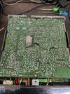
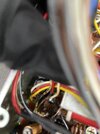
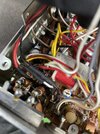
This radio has experienced a reverse polarity event, some time in the past. D55 looks like it burned completely off the top side of the board. D44 has been replaced, and it burned open the trace on the board, you can see where it was repaired by someone in the past with a jumper wire. I can’t tell if they replaced d44 with a zenner diode or an 1n4148. I’m not too worried about it for the time being. The end of the large red power wire that goes from the back of the board to the front on/off switch was charred and melted but ohms out good, so I desoldered it and slide some heat shrink over it. When d55, which is right under the power jack burned up, there was a bit off a fire back there. The insulation on the external speaker wires is charred as well as the three wires going to the cb pa switch.
 

Attachments

  • IMG_0245.jpeg
    IMG_0245.jpeg
    4.5 MB · Views: 13
  • IMG_0243.jpeg
    IMG_0243.jpeg
    1.5 MB · Views: 15
  • IMG_0242.jpeg
    IMG_0242.jpeg
    1.6 MB · Views: 13
No it’s not, it kinda looks like it in the picture, that’s a little bit of the lead of the talk back resistor that I clipped out. I corrected the wires that were passing under the antenna wire. I’m thinking about pulling c168 a ceramic disc cap and testing it. I’m looking at the schematic. It looks like the barrel of the ext speaker jack connects to c168, c240, c167 maybe?. And a wire that goes all the way to pin 3 of the mic jack.
 
This radio hasn't been converted from the original 5-pin mike socket to a 4-pin socket, has it?

73
No it has not, it’s still the original 5 pin socket. Today I even removed it, so I could do a good visual inspection of it and the pcb it’s mounted to. I even removed the dried Sony bond glue on l503 and 504, on the little mic jack pcb. I also removed the front faceplate and knobs. so I could remove the cb/pa switch and inspect it, make sure nobody put a resistor in there or anything crazy.

It may be hard to see in the pictures, but the wires that go to the internal speaker got charred, along with the three wires that go to the cb/pa switch, and two wires that ultimately go to mic jack. The out side of c167 is blackened. This all happened before I got the radio, I’m assuming it happened when d55 burned up. It’s almost like the was a small fire back the lol. But none of the wires seem to be shorted together, or are even touching.

At this point all I know to do is properly repair all the burned wiring and pull c167 and test it, and maybe some more of the ceramic discs.
 
I fixed the burnt internal speaker wires, even though the insulation was not burned off, and they ohmed out fine. Next I pulled c167, 168, and 169 they tested good on a little transistor parts tester, they measured well within 10%. I went over the schematic trying to reconfirm, that I had reconnected the wire they had cut on the mic gain pot, in the right place. I have continuity from it all the way to pin 1 on the mic socket. They had cut the wires that go to hi low tone switch an I reconnected them and it works. I pulled q53 and it tested good so I put it back in, I’m thinking about testing q43 and q47 also. I’ve got it inmy head now, that this problem is a failed component. But I’m far from a radio technician, but I’m not giving up. If I spend enough time on it, I will fix it.

So on this radio, if I have my antenna connected, with the mic unplugged. I get real receive audio out of both the internal and external speaker, just not really loud.I can actually hear stations on channel six. If I plug the mic in it gets loud like it should be.

I plan on checking some more disc caps, and changing some of the electrolytic. I still need to check the little disc cap on the mic socket pcb.

Does anyone think a failed transistor could be causing this problem.

I’m editing this to say that, with the mic unplugged I get receive audio out of both the internal and external speaker at the same time, when I plug a mic in I get loud audio out of just the external speaker.
 
Last edited:
I wonder if the external jack is shorted to the case or something, pull the wire that goes to pin 3 on the mic jack and see what changes.
Without it the ground side of the speaker and ext jack should be open nothing should be heard at all. If you still have sound or talkback follow the trace that wire goes to and look for anything shorted on that path. If not it should be on the mic jack board. 1st try seeing if the pin 3 line ungrounds or opens while keying the mic and go towards the mic from there.
Someone double check my thoughts here.
Edit: Nomad just suggested that right above, I didn't see ...
 
Looking from the speaker, towards the audio amp there are blocking caps and towards the mic it should be open while PTT is pressed. We should test that.

With the radio OFF, first ohm between one of the speaker terminals and board ground with PTT released (RX). You should see either 0 ohm or the speakers dc resistance (depending on which side of the speaker you ohm). Now, with the ohm meter probes between ground and the speaker terminal that showed 0 ohm, key the mic (radio still OFF). The resistance should rise rapidly.

Keeping the mic keyed (tape it down if you have to), allow some time for the ohm meter to charge all the associated capacitors and let it settle before reading. Once it settles, see if there is an open circuit or a very high resistance. Thats what we want, an open circuit or, at the very least, a high resistance from capacitor leakage, but not a low resistance.

If you see a lower resistance between the speaker and ground with the radio off and PTT keyed, a problem exists. Write down that resistance.

Since the speaker seems to be getting ground even with PTT pressed, I would be interested in knowing where the ground side speaker wire goes. Did the wire that should find ground via the mic get moved to a different ground?
 

dxChat
Help Users
  • No one is chatting at the moment.