
Here is probably the second-most popular mod to the Cobra 148GTL after unlocking the clarifier: Making a front-panel knob control the AM carrier level. The SWR Cal control is the obvious candidate. It helps that the control's resistance value is about perfect for this.
The pics are from the chinese main circuit board, the KEPC-332D used from the late 1990s to the early 2010's. The same setup applies to all 40-channel 148 radios but the exact physical locations and callout numbers vary from version to version. And there have been a lot of versions since 1979.
Parts list:
5) 1N4148 or equivalent general-purpose low-current diodes.
1) 10K 1/4W. resistor
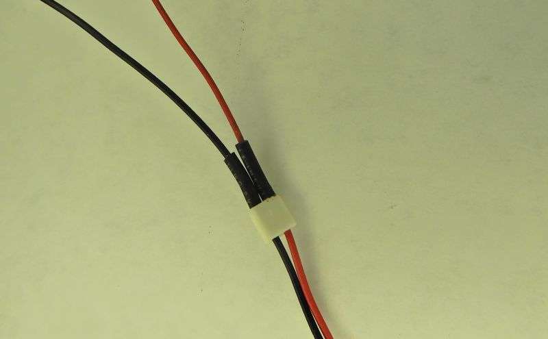
Insulating sleeve for lab-soldered wire splices and for the both the single and the four series diodes. Doesn't have to be shrink. Plain sleeve left over after stripping a wire works, too.
We'll start with re-activating the SWR meter after unhooking the Cal control from the original circuit board hookup.
Two of the SWR Cal control's wires connect to the circuit board at tiny white plastic "transition" connector. It's soldered to the pc board, marked "VR406". Unsolder it from the pc board.
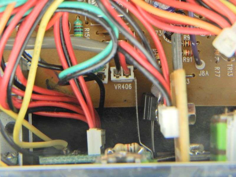
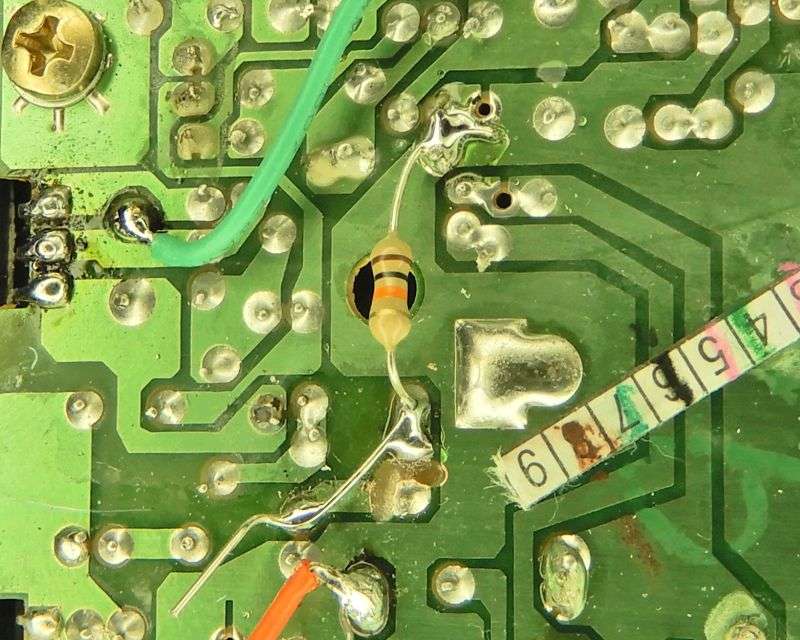
Once it has been removed, a 5.1k (or 4.7k, or 5.6k) resistor gets one lead bridged across the two holes left by the VR406 plug. The other end goes to ground.
The black wire is the clockwise (right) lug of the Cal control. The red wire is the wiper. We will need to extend the length of both to properly reach the AM modulator circuit near the rear of the radio.
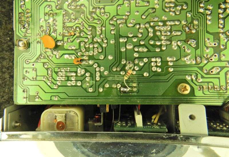
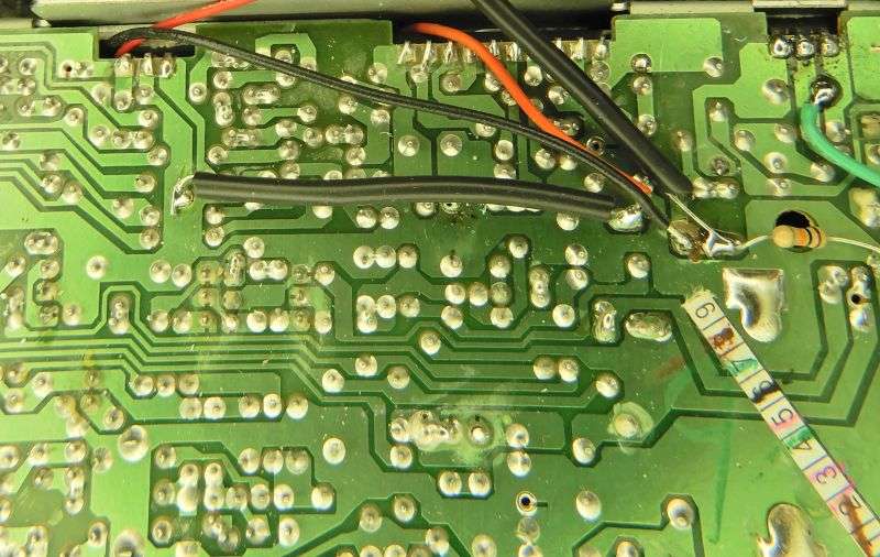
The end of the black wire connects to the wiper (center pin) of the radio's original carrier-set trimpot. First, that lug of the trimpot has to be isolated from the rest of the circuit. Requires cutting a trace to its left, and towards the rear of the radio. Isolating the trimpot's center pin requires severing the foil leading away from it in BOTH directions. The 10k resistor is now connected to the two ends of the severed trace so that it joins the two separated ends WITHOUT connecting back to the trimpot's center pin. Both these details appear below.
Next thing to do is solder four 1N4148 diodes end-to-end. This string of diodes will take the place of a "minimum carrier" trimpot. You don't really need a picture showing how to solder four diodes in series, do you?
The minimum carrier with the SWR CAL knob turned far left will be around 1/10 of a Watt with no need for an added trimmer pot.
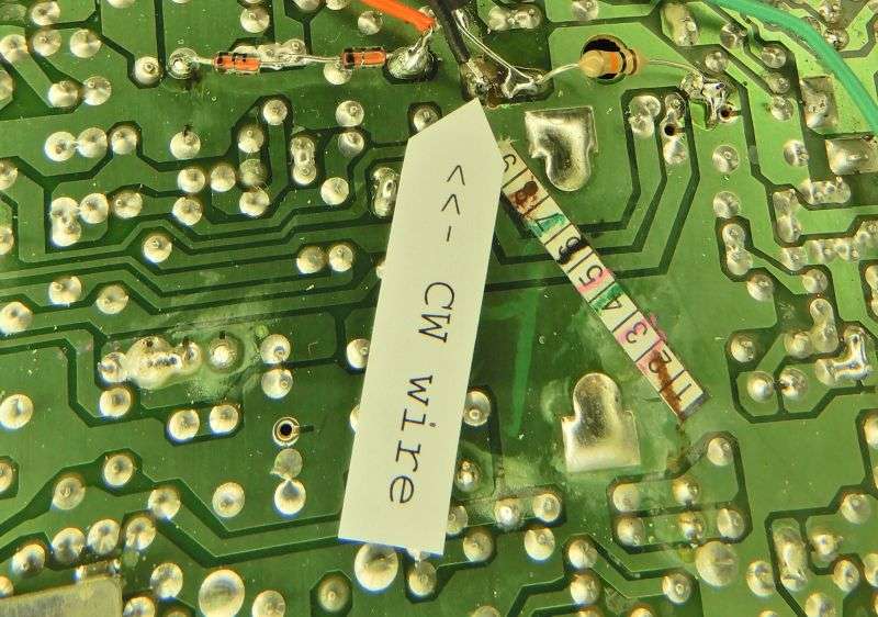
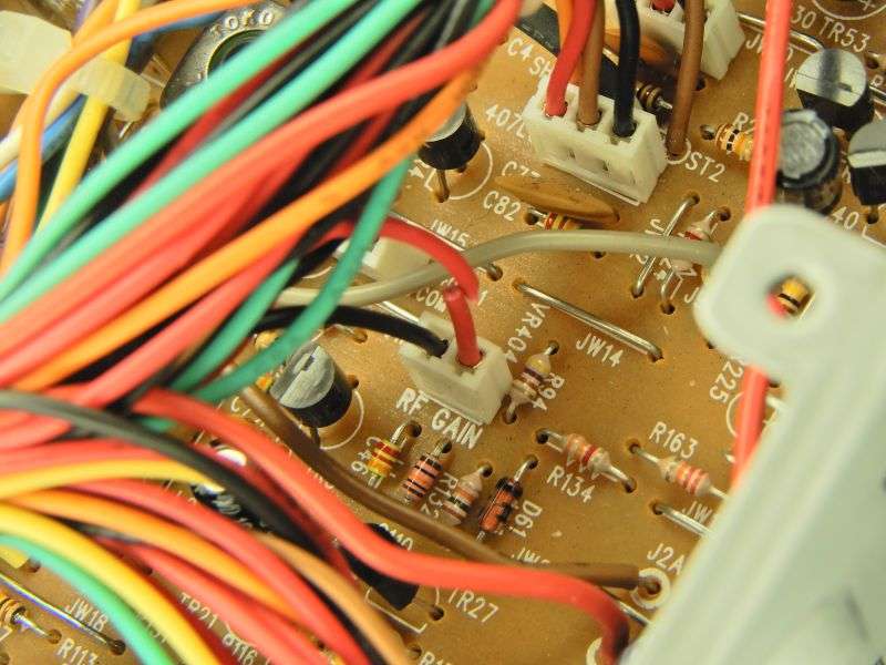
Next we need to identify and extend the length of the CCW (left) wire that connects us to the CCW lug of VR406. Oddly enough, this wire connects to the circuit board at a white 2-wire transition plug labeled "VR404". Cut the red wire as shown, and lap-solder an extension wire that will reach the underside of the pc board beneath the factory carrier trimpot. The transition plug labeled "VR404" has one wire from the SWR Cal control, the counterclockwise (left) lug. This is the red wire on this connector. The black wire gets left alone. It's connected to the RF Gain control like it's labeled. This wire was extended in the same red color, but that won't matter. Needs to reach the original carrier trimpot area.
The far end of this new wire goes to the outside-most lug of the original carrier trimpot. The non-banded end of the series string of diodes also solders here.
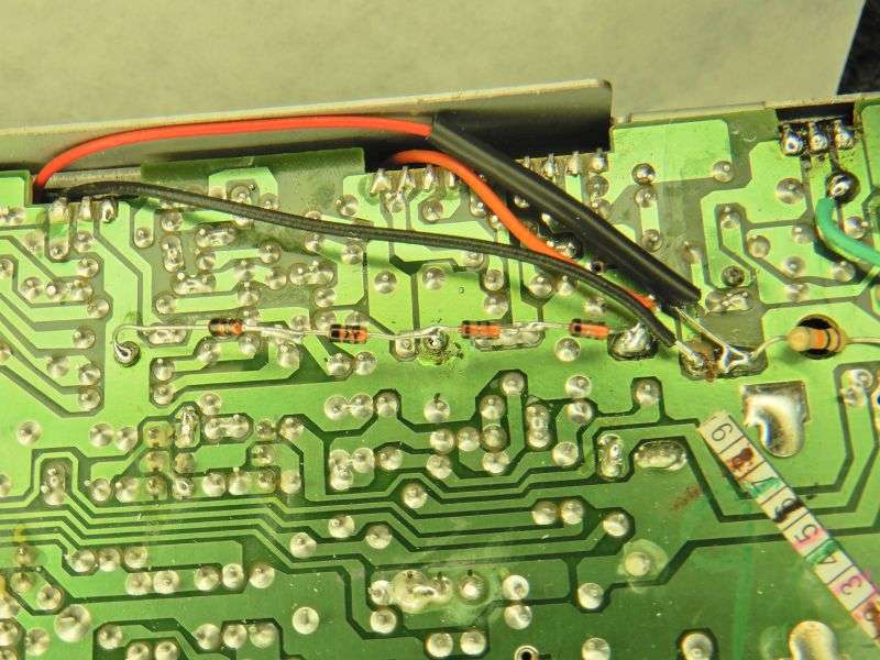
The banded end of the diode string goes to a ground foil. Didn't get a proper shot of that. We slide an insulation sleeve over them.
Finally, we connect the wire that leads back to the wiper lug of VR406. In this pic it's red. The fifth 1N4148 gets put in line with this wire. Anode (no banded) end goes to the free end of the wire. Cathode (band) goes to the hot side of the 10k resistor.
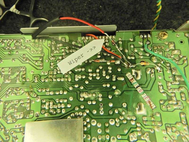
A sleeve over this one will serve to keep it out of trouble before it can touch any foil traces.
What remains now is first, to decide if you really want to perform the "power jump" on this radio. If you do disconnect the bias-test wire for the final from its test point and hook it directly to the main B+ power be sure to insert a current meter and make sure the final bias trimpot is set to a proper 60 mA.
No, I didn't include that here. This setup works just fine with the final's power source wired factory stock, plugged into the bias-test jumper pin. But someone who wants to see the same PEP on AM as they do on sideband will obtain it that way. The factory setup causes a small voltage drop in the AM modulator transistor feeding into the final. This reduces the final's peak power by a few Watts. Not enough to matter, but people want what they want.
The original carrier trimpot new serves to set the max carrier limit with the Cal knob turned full up. Minimum should be the same wherever the max power gets set.
This is what we have used for decades. Feel free to mod or embellish to your heart's content. The customers like it, and that's what we pay attention to.
73
The pics are from the chinese main circuit board, the KEPC-332D used from the late 1990s to the early 2010's. The same setup applies to all 40-channel 148 radios but the exact physical locations and callout numbers vary from version to version. And there have been a lot of versions since 1979.
Parts list:
5) 1N4148 or equivalent general-purpose low-current diodes.
1) 10K 1/4W. resistor
Insulating sleeve for lab-soldered wire splices and for the both the single and the four series diodes. Doesn't have to be shrink. Plain sleeve left over after stripping a wire works, too.
We'll start with re-activating the SWR meter after unhooking the Cal control from the original circuit board hookup.
Two of the SWR Cal control's wires connect to the circuit board at tiny white plastic "transition" connector. It's soldered to the pc board, marked "VR406". Unsolder it from the pc board.
Once it has been removed, a 5.1k (or 4.7k, or 5.6k) resistor gets one lead bridged across the two holes left by the VR406 plug. The other end goes to ground.
The black wire is the clockwise (right) lug of the Cal control. The red wire is the wiper. We will need to extend the length of both to properly reach the AM modulator circuit near the rear of the radio.
The end of the black wire connects to the wiper (center pin) of the radio's original carrier-set trimpot. First, that lug of the trimpot has to be isolated from the rest of the circuit. Requires cutting a trace to its left, and towards the rear of the radio. Isolating the trimpot's center pin requires severing the foil leading away from it in BOTH directions. The 10k resistor is now connected to the two ends of the severed trace so that it joins the two separated ends WITHOUT connecting back to the trimpot's center pin. Both these details appear below.
Next thing to do is solder four 1N4148 diodes end-to-end. This string of diodes will take the place of a "minimum carrier" trimpot. You don't really need a picture showing how to solder four diodes in series, do you?
The minimum carrier with the SWR CAL knob turned far left will be around 1/10 of a Watt with no need for an added trimmer pot.
Next we need to identify and extend the length of the CCW (left) wire that connects us to the CCW lug of VR406. Oddly enough, this wire connects to the circuit board at a white 2-wire transition plug labeled "VR404". Cut the red wire as shown, and lap-solder an extension wire that will reach the underside of the pc board beneath the factory carrier trimpot. The transition plug labeled "VR404" has one wire from the SWR Cal control, the counterclockwise (left) lug. This is the red wire on this connector. The black wire gets left alone. It's connected to the RF Gain control like it's labeled. This wire was extended in the same red color, but that won't matter. Needs to reach the original carrier trimpot area.
The far end of this new wire goes to the outside-most lug of the original carrier trimpot. The non-banded end of the series string of diodes also solders here.
The banded end of the diode string goes to a ground foil. Didn't get a proper shot of that. We slide an insulation sleeve over them.
Finally, we connect the wire that leads back to the wiper lug of VR406. In this pic it's red. The fifth 1N4148 gets put in line with this wire. Anode (no banded) end goes to the free end of the wire. Cathode (band) goes to the hot side of the 10k resistor.
A sleeve over this one will serve to keep it out of trouble before it can touch any foil traces.
What remains now is first, to decide if you really want to perform the "power jump" on this radio. If you do disconnect the bias-test wire for the final from its test point and hook it directly to the main B+ power be sure to insert a current meter and make sure the final bias trimpot is set to a proper 60 mA.
No, I didn't include that here. This setup works just fine with the final's power source wired factory stock, plugged into the bias-test jumper pin. But someone who wants to see the same PEP on AM as they do on sideband will obtain it that way. The factory setup causes a small voltage drop in the AM modulator transistor feeding into the final. This reduces the final's peak power by a few Watts. Not enough to matter, but people want what they want.
The original carrier trimpot new serves to set the max carrier limit with the Cal knob turned full up. Minimum should be the same wherever the max power gets set.
This is what we have used for decades. Feel free to mod or embellish to your heart's content. The customers like it, and that's what we pay attention to.
73
