I am not working on a radio, just looking for a little theory.
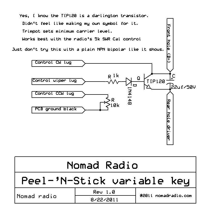
When I think of varying the dead key, I immediately think about varying the regulator that controls the collector voltage of the finals. However, i assume that if it were done that way, every time the collector voltage was adjusted, the modulation depth would also need to be adjusted (somehow asymmetrically).
I am hoping someone can explain to me the magic under the hood that allows the easy installation of a pot to vary the dead key without having to worry about transitioning from undermodulation to boxcars when using it. It doesn't seem like a simple thing to add properly.
Thanks!