
You are using an out of date browser. It may not display this or other websites correctly.
You should upgrade or use an alternative browser.
You should upgrade or use an alternative browser.
-
You can now help support WorldwideDX when you shop on Amazon at no additional cost to you! Simply follow this Shop on Amazon link first and a portion of any purchase is sent to WorldwideDX to help with site costs.
-
A Winner has been chosen for the 2026 July 4th Retevis RA89R Giveaway! Click Here to see who won!
What is this?
- Thread starter HomerBB
- Start date
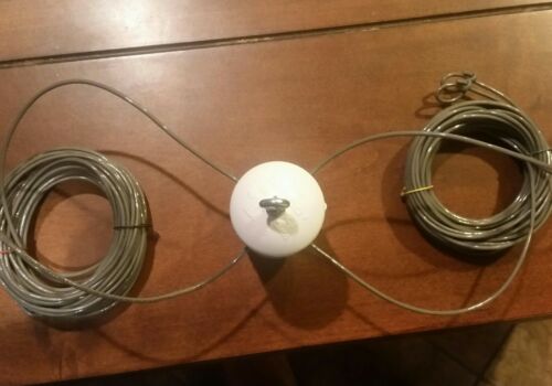

It ain't no turnstile.
It is only two one wavelength long elements per side.
Each element is fed in the middle of the one wavelength wire.
Each one wavelength wire is bent at 90° in the middle.
One of the one wavelength wires is connected in the middle to the coax center conductor.
One of the one wavelength wires is connected in the middle to the coax braid.
The 1:1 balun is at the feedpoint.
It ain't no turnstile.
Homer, on second look I think you are right. Back to the drawing board.
Yep.Homer, on second look I think you are right. Back to the drawing board.
It's an odd one.
Each side is 1/2 the whole antenna.
No phased feed. One coax. Braid in the middle of a 34' 5" wire.
Center conductor in the middle of another 34' 5" wire.
Yea, using a 1 : 1 balun on those 1/2 wave legs was the first thing I thought was out of sorts..If the elements were half as long, it would be a turnstile antenna of some sort.
But half-wave long wires should give it a horrendously high feedpoint impedance.
I'm baffled.
73
Anytime you have to use a whiteboard to explain something, I leave the room for more coffee.
It is a remotely operated wallet lever. It opens your wallet and send you money.

VERTICAL PLOT, Notice both have very high swr, I did not try to solve for swr, simply used 11.05 meters as one full wave.
Good job. As expected, “Z” is extremely high on full wave dipoles. As is SWR. The proof is in the pudding. Or the model, I guess I should say.
dxChat
- No one is chatting at the moment.
