• You can now help support WorldwideDX when you shop on Amazon at no additional cost to you! Simply follow this Shop on Amazon link first and a portion of any purchase is sent to WorldwideDX to help with site costs.

What W8JI says about a 1/4 wave vs. 5/8 wave

marconi , the quote was from w8ji .
End-fed Vertical and J-pole

others have had a different experience comparing their imax to other 5/8s' with ground elements than the results w8ji got . but as bob pointed out , i did miss something .

i still can't makes heads or tails of modeling programs . :headbang:headbang:headbang

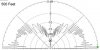
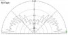
Here is my model of my center fed 5/8 wave dipole showing the antenna with a mast attached and one that is insulated from the mast by 6". BTW, I also made the feed point source at the end like W8JI did, and I got very similar results to the center fed. All I did was attach the mast to the antenna and the pattern went funky like Bob would tell us. An end fed antenna attached to conductive mast without some method to decouple the antenna from the feed line and or mast...will show to be messy with the model and maybe work about the same. W8JI suggested that he modeled a similar antenna to the Imax, and also mentions that he did the matching section...and he still shows the problem. Why is that?

That's no Imax that I know of and if it was every fool that ever bought one would be returning it, just look at the pattern he shows us.

On the other hand, if you took the radials off of an I-10K, it would probably suffer some in the performance category, and if not the match would likely suffer badly, and the radio would tend to shut down in output enough to be noticable.

Ask yourself BM, is that the antenna response you saw when your buddies had their Imax's up without radials or a choke? I don't think so, no matter what else y'all thought about it at the time. W8JI maybe be technically correct, but he is talking way over our heads in most cases, and you'll never know if what he describes is a problem of effectiveness or efficiency, and they're not the same thing.

For sure you won't learn much just looking at the pictures without at least understanding the captions.

View attachment IMG.pdf
 
Last edited:
FM broadcast antenna manufacturers publish free space models for good reason. It makes it easy separate differences in performance related to antenna design versus differences in performance related to height above ground. Without free space you can't tell if power being radiated at undesired angles is a result of antenna design or ground reflections.

The higher above ground, the more secondary lobes are developed at angles that can vary widely with height. At the same time, the primary lobe will continue to drop closer to the horizon until it levels off many wavelengths above ground. This effect is fairly predictable with wavelength and soil type in terms of the primary lobe for line of sight propagation. Modeling at various heights above real ground can be a useful tool if you desire to use secondary lobes to target specific angles for DX propagation.

Results in free space do transfer over to real world and represent antenna performance without the variables associated with different mounting heights. Once a model is designed to provide peak gain at zero degrees in free space, altering the design will not typically improve performance on the horizon when mounted over real ground. However, placing the antenna above real ground always provides more gain then the free space model.

If this sounds like hocus pocus and you think free space is useless because no one mounts their antenna in free space, remember the characteristics described apply to all antennas. For example a half wave horizontal dipole mounted one wavelength above ground has several db over a dipole as W8JI and many others have pointed out. Once you understand this, then it becomes clear why we need free space to determine a relative fixed gain reference point for the dipole and the same playing field to compare other antennas against it.

Will your results vary from one installation location to another? Of course they will. At the same time the free space model provides significant information in which to base your predictions as to how a particular antenna should perform in your specific installation. Even things like adding a mast in free space show accurate results. In the case of the Sigma IV, the mast actually tightens the beamwidth and focuses more gain at 0 degrees in free space or at the horizon over real ground.
 
Below are EZNEC plots of a single bay vertical FM broadcast dipole at 98 MHz shown at 500 feet, 50 feet and free space. There are significant differences that prevent the antenna from functioning as if it were in free space even at 50 wavelengths in height. Otherwise we would never need options like beam tilt or null fill.
 

Attachments

  • 500 Feet copy.jpg
    500 Feet copy.jpg
    43.7 KB · Views: 7
  • 50 Feet copy.jpg
    50 Feet copy.jpg
    40.8 KB · Views: 4
  • Free Space copy.jpg
    Free Space copy.jpg
    52.6 KB · Views: 5
i don't know about w8ji's accuracy but it seems pretty clear to me what he is claiming,
he gives two examples of the no radial imax type antenna, first with a worst case scenario mast/feedline length and also with a best case scenario mast feedline length,
he is a little misleadin as he makes comparisons with his best effort 1/4wave model,


i don't have a problem with freespace plots as a level playing field for comparisons or when an antenna is very high above earth,

cebik wrote an interesting article on upper hf monopoles what he decriibes as "a poorly grounded speculation"

http://www.cebik.com/content/gp/58-3.html

http://www.cebik.com/content/a10/wire/high.html
 
I research a lot before I put money into a piece of equipment.

I read reviews from several sites, cb and ham alike.

Here is a link to imax-2000 with pages of reviews.

Some are good some not so good but it is enough to get an idea of hope this antenna performs in real world use.

http://www.eham.net/reviews/detail/1376

Based on the reviews the Imax 2000 arrived yesterday by UPS ground and will be on the tower at 70 feet this weekend if the weather permits.

I hope it performs as well as some of the 5/8 wl antennas I have home brewed, but the home brewed ones have a lot more weight than the imax 2000.
 
Last edited:
Below are EZNEC plots of a single bay vertical FM broadcast dipole at 98 MHz shown at 500 feet, 50 feet and free space. There are significant differences that prevent the antenna from functioning as if it were in free space even at 50 wavelengths in height. Otherwise we would never need options like beam tilt or null fill.


Something does not look right. The 50 ft and 500 ft patterns lead one to believe there is absolutely no radiation below zero degrees elevation and we know that is not the case. Null fill and beam tilt is generally rarely used and only when the antenna is at a great EHAAT and needed to fill in relatively close in.Beam tilt rarely exceeds a couple degrees. The general shape of the 50 and 500 ft patterns even with the multiple nulls generally follows the same overall shape as the free space pattern shown above zero degrees elevation and hence my statement that they are essentially the same.

Where did you get those patterns? I tried to link to the images to find out a bit more about them but couldn't.

Captain, I see your point about the above ground pattern having similarities with the shape of the free space from 0 to 180 degrees. I just modeled the dipole at these heights today using EZNEC+ so we could see the differences. They are only online here so far. I understand we should expect to see some downward radiation with the real ground models but using these programs never seems to display that result unless the model is in free space.
 
Shockwave, I wouldn't get too concerned and question what you see in the example you made. It is natural for guys to make an argument when they just give us words.

I did the same thing you did and my results were similar, except my 50' foot model didn't develop all the narrow lobes and nulls until I reached about 100' feet. My 500' foot model looked almost identical. Could that be the difference in Eznec5 and Eznec5+.

Did you include a mast with your model over real Earth? And did you set your model to zero for all losses before running the free space pattern? That could be some of any difference I might have noted. I didn't set the models side by side, so there maybe be more difference that I suggested, but IMO, they looked alike.

I don't know how Eznec handles the issues that QRN noted, so maybe he can give us some examples of his contention in this regard. I might just learn something new, and that would be good.
 
Marconi,

The only reason why you didn't see as many nulls and lobes as my examples are the result of the different frequencies used in the models. Your models were probably done on HF while mine were on VHF band II. Shorter wavelengths produce more ground reflections for the same physical height above ground. I did not use a mast or feedline intentionally on this model because I wanted the only distortion in the pattern to be the result of ground reflections. There are no significant losses in the model and it's one of the easiest ones to build.

What Captain Kilowatt says about downward radiation in antennas mounted above real ground is completely true. In fact it posses a significant problem for some broadcast stations concerning safe RF exposure levels to people in the vicinity of the tower base. I suspect this characteristic is more common above the HF spectrum and with higher antenna elevation. EZNEC+ has never shown me a drop of radiation below 0 degrees over real earth in any of these models even though I know it exists to some degree.

I agree that Eznec doesn't seem to ever show RF below the horizon when set to a real Earth pattern, and I didn't mean to suggest that just because this is what Eznec shows, is what happens with a real antenna over Earth.

But, I'm dubious that an antenna connected to Earth, within reason, will ever be totally free of Earth's ground affects on the pattern, such as not to alter the free space pattern. That is unless we are supposed to be considering "free space" as installing an antenna in a flat open field for many wavelengths.

On the other hand I have seen Eznec free space model patterns that showed the maximum RF below the horizon...with a -5* degrees for example. I think I posted one in this thread or my New Top One thread.
 
EZNEC+ has never shown me a drop of radiation below 0 degrees over real earth in any of these models even though I know it exists to some degree.

Use ground, but put the antenna at Z"0". 4NEC2 pops up some alarms or something, I'll have to do it again. But it seems the lobes are there, just not modeled.

EDIT________
Because of the funky scaling while building a beam I always drop the antenna to Z0 to make changes. I've accidentally ran it effectively on the ground a couple times.
 
Last edited:
Yeah, and I live in a big ole hole :glare: The holler is so deep, it's called moss holler if that is any kind of indication :censored:

ya me 2. have you messed around with 1/4 waves vs 5/8 waves?
what were your results? at times seems my mobile with a 1/4
whip does equally as good as my base 5/8 wave mounted low
just got wondering
 
ya me 2. have you messed around with 1/4 waves vs 5/8 waves?
what were your results? at times seems my mobile with a 1/4
whip does equally as good as my base 5/8 wave mounted low
just got wondering

No, no I haven't. The only thing I ever had on the old tower was 5/8 gp's or yagis. The only thing I've ever had on the truck was Wilson base loaded antennas. Besides the tower height, the tower base is a good 30' up a hill from the driveway, so there would be no way to make any real comparisons if I wanted to.
 
Use ground, but put the antenna at Z"0". 4NEC2 pops up some alarms or something, I'll have to do it again. But it seems the lobes are there, just not modeled.

EDIT________
Because of the funky scaling while building a beam I always drop the antenna to Z0 to make changes. I've accidentally ran it effectively on the ground a couple times.

If you put the antenna over real ground at Z 0 doesn't this place the antenna directly on top of the ground? This would remove the multiple lobes and nulls created by ground reflections but it doesn't seem to reveal the slightest downward radiation below 0 degrees.
 

dxChat
Help Users
  • No one is chatting at the moment.