
You are using an out of date browser. It may not display this or other websites correctly.
You should upgrade or use an alternative browser.
You should upgrade or use an alternative browser.
-
You can now help support WorldwideDX when you shop on Amazon at no additional cost to you! Simply follow this Shop on Amazon link first and a portion of any purchase is sent to WorldwideDX to help with site costs.
-
A Winner has been chosen for the 2026 July 4th Retevis RA89R Giveaway! Click Here to see who won!
Wire in an external PTT line to a CB radio
- Thread starter Xjeepguy
- Start date

I want an external PTT line to key a tube amplifier. I already have a ARB 704 Ameritron relay/buffer so would feed into that and that safely keys an amp.Just to key the radio?
or key an Amp?
what do you want it for?
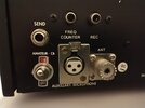
I have and it worked out well for me. I have and older 2517 that I kinda Frankensteined with mods or improvements to my desire. With that large of a box and chassis I had plenty of room to experiment. All I did was I tapped into the microphone jack itself on the inside of the radio. I left everything the way it was stock but I just added one wire to the hot or ptt pin and one wire to the negative pin or what ever pin it is that it used for ptt on the mic jack. I drilled a hole on the rear of the radio and added a 1/4 phone jack. Then all I had to do was make or buy a momentary push button to use as a ptt switch. I even wired an xlr jack to the back of the radio so I could use a studio mic without all of the adapters. Both worked out well. The best part is you can still revert back to stock if you wanted to or just hook up the studio mic in the rear of the radio. But that also gives you an input to run rack gear into the rig to sound even better. People will say you shouldn't do that because it's not the proper way. For me it was an experiment that worked just fine. In the picture it shows I added the SEND jack which is the ptt. I also added the xlr jack and extended frequency coverage more than what is on the front of the radio.Anyone ever done it? I'm referring to like what would be the aux PTT line like in the back of an amateur rig . Let's use the 2950 or Stryker 955 for examples . Anyone ever do this ?
Attachments
I sell a pc board with a relay that uses the radio's internal "transmit-only" switched voltage to activate the relay. It has two outputs. How many users have two amplifiers in line to key this way? Enough of them asked to get the feature added. The relay has enough current/voltage rating on the contacts to key whatever amplifier you have direct, no keying box needed.
https://www.ebay.com/itm/1143644460...d=link&campid=5336136228&toolid=20001&mkevt=1
And if you want to just roll your own, I can probably dig up the schematic for anyone interested.
73
https://www.ebay.com/itm/1143644460...d=link&campid=5336136228&toolid=20001&mkevt=1
And if you want to just roll your own, I can probably dig up the schematic for anyone interested.
73
This page shows how to install in a 2950-based base radio like a 1990s SaturnTurbo or 2990.
http://www.nomadradio.com/OldNomadWebPages/KBTurbo/index.htm
73
http://www.nomadradio.com/OldNomadWebPages/KBTurbo/index.htm
73
I'd love to add a PTT send key jack to my 955HPC V2. Has anyone done this type of mod on the newer Stryker 955? If so, can you please share the mod instructions?
This mod would then allow me to use a QRM x-Phase eliminator and combat the QRM from my house and my neighbors.
Cheers,
Frank
This mod would then allow me to use a QRM x-Phase eliminator and combat the QRM from my house and my neighbors.
Cheers,
Frank
I am thinking about adding a relay to the PTT ground shorting pins, externally on the microphone cord. Have the relay coil connected to the same incoming 13.8v positive lead and the other end of the relay coil to the ground (pin 3 on the four pin connector). This will trigger the relay to act as a switch.I'd love to add a PTT send key jack to my 955HPC V2. Has anyone done this type of mod on the newer Stryker 955? If so, can you please share the mod instructions?
This mod would then allow me to use a QRM x-Phase eliminator and combat the QRM from my house and my neighbors.
Cheers,
Frank
Seems harmless as the relay only requires 30mA to energize the relay coil.
Any reason this would not be recommended?
Feeding 13.8 Volts into the transmit pin of the radio's mike socket through the relay coil may fry a thing or two. When this is done in the RCI 2950/70/90/95 radios with the LCD computer display it will **FRY** the radio's computer. The mike jack's transmit pin leads to one input pin on a 5-Volt computer chip. Pumping 13.8 into it by way of the relay coil has been shown to fry the computer for good more than once.Have the relay coil connected to the same incoming 13.8v positive lead and the other end of the relay coil to the ground (pin 3 on the four pin connector)
Might be. Haven't seen this problem with Strykers, but we don't see a lot of them in the first place. But Galaxy DX22, DX2527, RCI 2950, 2970, 2990, 2995, Eagle 5000 will all fry the radio's brain if anything more than 5 Volts DC feeds into pin 3 of the mike socket.Seems harmless
We sell a safer solution on fleabay, ready to install.
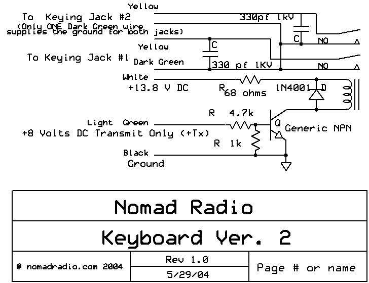
Here's the schematic:
73
We sell a safer solution on fleabay, ready to install
I will insert a "plug" here for those who don't want to roll there own.
Nomad helps people here often, I don't mind supporting his cause.
Items for sale by originalnomadradio | eBay
Shop eBay for great deals from originalnomadradio!
www.ebay.com
73
Jeff
Any chance of a gerber file?Feeding 13.8 Volts into the transmit pin of the radio's mike socket through the relay coil may fry a thing or two. When this is done in the RCI 2950/70/90/95 radios with the LCD computer display it will **FRY** the radio's computer. The mike jack's transmit pin leads to one input pin on a 5-Volt computer chip. Pumping 13.8 into it by way of the relay coil has been shown to fry the computer for good more than once.
Might be. Haven't seen this problem with Strykers, but we don't see a lot of them in the first place. But Galaxy DX22, DX2527, RCI 2950, 2970, 2990, 2995, Eagle 5000 will all fry the radio's brain if anything more than 5 Volts DC feeds into pin 3 of the mike socket.
We sell a safer solution on fleabay, ready to install.
Here's the schematic:
73
I’m in the uk and the postage is horrendous on the eBay.
I’ve got a lot of guys over here who would benefit from this cool idea
Hmm. Hadn't thought of that. Started out using expresspcb.com 23 years ago, and their proprietary CAD-file format sorta locks you in to uploading to their site. They have loosened up and will now supply standard gerber files along with the finished pcbs. Just one issue. This pattern was a small part of a larger board. Ordering fifty of a board with 7 or 8 small gadgets like this on it is a lot cheaper than having them made individually.Any chance of a gerber file?
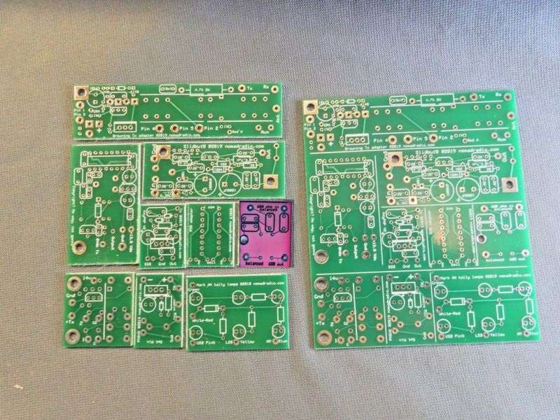
We cut them apart with a sheet-metal shear. The gerber files for that order show the whole pattern of 7 or 8 small pcbs on one large piece.
And extracting just that part of a gerber file is outside my wheelhouse.
Making it truly "open source" would work better if I didn't use a supplier with a proprietary file format.
Oops.
73
It's a cool offer, but the exact combination of all those small board patterns is determined by what sold out during the previous six months or year. It's unusual to order the exact same board twice. Some of the small board in the pic above sold out, some did not.
I really should modernize my design process. It's 20 years or more out of date. So far we have not used a single SMT part in anything we sell. SMT is designed for machine assembly, and is not efficient for small-batch assembly by hand. Not sure the through-hole parts are any more efficient, but they're a lot more practical, given the skills of the folks I hire to assemble and solder them.
Maybe the day will come when one or more of our gadgets will get redesigned for SMT and get machine assembled/soldered by a contract outfit.
Maybe.
Thanks for the offer, though.
73
dxChat
- No one is chatting at the moment.
