
You are using an out of date browser. It may not display this or other websites correctly.
You should upgrade or use an alternative browser.
You should upgrade or use an alternative browser.
-
You can now help support WorldwideDX when you shop on Amazon at no additional cost to you! Simply follow this Shop on Amazon link first and a portion of any purchase is sent to WorldwideDX to help with site costs.
Wiring a 4 wire D-104 to a CPI 2000 cb base
- Thread starter danmcclain
- Start date

This should help. I don't know which stand you are using.
 elecurls.tripod.com
Here is the schematic for the CPI2000
Astatic D-104 Microphones
Here is the schematic for the CPI2000
Thanks, but I can't read a schematic to save my life.... DanThis should help. I don't know which stand you are using.
Astatic D-104 Microphones
Here is the schematic for the CPI2000
From this thread: https://www.worldwidedx.com/threads/cpi-2000-mic-wiring.29842/
CPI 2000 mic wiring:
Pin 1 is Audio
Pin 2 is Ground
Pin 3 is TX PTT
Pin 4 is TX PTT return
Connect pins 3 and 4 through the PTT switch to make the radio transmit.
Which, I think, in D104 T-UG8 four wire mic wire colors would be:
Pin 1 Audio
Pin 2 Shield & Blue
Pin 3 Red
Pin 4 Black
Then set the D104 to relay keying (the E/R switch to R).
That's based on the diagrams from this site:
I've never actually tried this, so proceed at your own risk. Not responsible if your radio explodes or opens a portal to an alternate dimension, etc.
I counted the shield as a wire, so 3 wires and a shield, thanks for the help... DanFrom this thread: https://www.worldwidedx.com/threads/cpi-2000-mic-wiring.29842/
CPI 2000 mic wiring:
Pin 1 is Audio
Pin 2 is Ground
Pin 3 is TX PTT
Pin 4 is TX PTT return
Connect pins 3 and 4 through the PTT switch to make the radio transmit.
Which, I think, in D104 T-UG8 four wire mic wire colors would be:
Pin 1 Audio
Pin 2 Shield & Blue
Pin 3 Red
Pin 4 Black
Then set the D104 to relay keying (the E/R switch to R).
That's based on the diagrams from this site:
I've never actually tried this, so proceed at your own risk. Not responsible if your radio explodes or opens a portal to an alternate dimension, etc.
From the owners Manual:

There is no ground involved in relay PTT switching.
It sounds like you have a T-UG8 base on your D104.
Stock colors would be:
Pin 1 - White
Pin 2 - Shield (bare copper wrapped around the white wire)
Pin 3 - Black (PTT RX)
Pin 4 - Red (PTT TX)
In your case, with a 4 wire D104, you are ok as long as the switch stays in the "Relay" position. But if some how the mic was switched to the"Electronic" position and you key the mic, you will ground out your PTT circuit and damage the cpi2000.
To be extra safe, you could disconnect the "Brown" wire that goes from the E/R switch to the ground lug. It doesn't matter which end you disconnect. This will effectively disable the "electronic" switching and your radio won't be damaged if accidently put in the "Electronic" position (it just won't key).
If you have a mic that doesn't have an elec/relay"switch" and you need it to "relay" switch, you need to remove the PTT common wire and solder the RX wire where it was located.
You don't have to be able to read a schematic, just look at the contacts (and the wires connected to them) in the microphone. Wire color can be dangerous to go by if the mic doesn't have the original mic cord on it (like a LOT of older mics).
Good Luck.
Attachments
Last edited:
Thanks, but I can't read a schematic to save my life.... Dan
Thank you for the info 999.... DanThis should help. I don't know which stand you are using.
Astatic D-104 Microphones
Here is the schematic for the CPI2000
Many thanks for the info... DanFrom the owners Manual:
View attachment 61963
There is no ground involved in relay PTT switching.
For safety sake, you should NOT connect the Blue wire (PTT Common) to pin 2.
As long as the "relay" switch is working properly, you are fine. But if some how the mic was switched to "Electronic" and the Blue wire was still connected to the shield/pin 2, then you will ground out your PTT circuit and damage the radio.
If you have a mic that doesn't have an elec/relay"switch" and you need it to "relay" switch, you need to remove the PTT common wire and solder the RX wire (in this case Black) where it was located.
You don't have to be able to read a schematic, just look at the contacts (and the wires connected to them) in the microphone. Wire color can be dangerous to go by if the mic doesn't have the original mic cord on it (like a LOT of older mics).
Good Luck.
Also, not to disagree with TM86, in relay switching the 2 connections used for PTT can be reversed; so pins 3 & 4 can be either color Red or Black - it doesn't matter. All that matters is that they "connect" when the mic is keyed.
Thanks for the info... DanAlso, not to disagree with TM86, in relay switching the 2 connections used for PTT can be reversed; so pins 3 & 4 can be either color Red or Black - it doesn't matter. All that matters is that they "connect" when the mic is keyed.
I made a mistake and wired a non-amp D-104. I would like the wire a 5 wire with sheild Night Eagle D-104 to my CPI 2000, sorry about that.... DanThanks for the info... Dan
Don't worry about disagreeing with me, I might be wrong.Also, not to disagree with TM86, in relay switching the 2 connections used for PTT can be reversed; so pins 3 & 4 can be either color Red or Black - it doesn't matter. All that matters is that they "connect" when the mic is keyed.
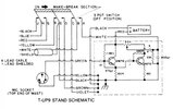
So, your Night Eagle D-104 uses the T-UP9 stand. It has 5 wires + shield and no E/R switch.
For stock colored wiring:
To make it work for "relay" switching, simply solder the Blue & Black wires together on the same pin (3 or 4 doesn't matter) and the Red wire on the other pin (3 or 4)
For Relay switching on a CPI2000:
Pin 1 - White (audio)
Pin 2 - Shield (ground)
Pin 3 - Blue & Black (PTT)
Pin 4 - Red (PTT)
Yellow wire - no connection
Attachments
Many thanks for the info... DanSo, your Night Eagle D-104 uses the T-UP9 stand. It has 5 wires + shield and no E/R switch.
For stock colored wiring:
To make it work for "relay" switching, simply solder the Blue & Black wires together on the same pin (3 or 4 doesn't matter) and the Red wire on the other pin (3 or 4)
For Relay switching on a CPI2000:
Pin 1 - White (audio)
Pin 2 - Shield (ground)
Pin 3 - Blue & Black (PTT)
Pin 4 - Red (PTT)
Yellow wire - no connection
I hope you enjoy your 2 CPI 2000's as much as I enjoy my 2. Arguably, the best "legal" FCC type accepted CB ever made and that includes Browning, Tram, Stoner, ARF, SBE, Uniden (Although I do love the UPD-858 deluxe SSB chassis), etc.
Having said that, they are pushing 45 years old and even though only the best available components were used in them, the E Caps should be replaced. It is a PITA because they use a double sided circuit board, but use some quality low ESR caps (Panasonic, Nichicon, etc.) and the radio will still be working 40 years from now.
Good Luck.
dxChat
- No one is chatting at the moment.