• You can now help support WorldwideDX when you shop on Amazon at no additional cost to you! Simply follow this Shop on Amazon link first and a portion of any purchase is sent to WorldwideDX to help with site costs.

Need help with side mic cobra 29 Ltd classic

red97k1500

Well-Known Member
Nov 26, 2012
359
291
73
texas
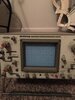
I recently picked up a 1990 model cobra 29 Ltd for very cheap, I’m not much of an Am’er, but I thought what the heck I’ll try out one of these Philippines cobra 29’s... it is dirty looks like it has sat up for years etc, in poor to fair cosmetic condition.

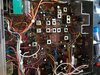
So I pull of the covers, spend 15 mins looking it over, it looks fairly untouched, d11 is clipped, one coil is just slightly spread. The slug is still in l14. But it does look like somebody has messed with l17 because the core was sticking about halfway above the top of the can and the plastic threads had come up with it.

So I plug it in and fire it up. it powers on, the channel display is a little flaky . A couple of segments arnt lighting up. I have noise coming out of my external speaker. But I have no tx, no carrier or modulation. So I do the classical hack shack parts shotgunning right off the bat.... so I spend the next two hours changing every single electrolytic cap in the radio.i used new rubycon and Nichicon capacitors, and about 3 or 4 of those cheap jwc ones.

So once I’m finished, I fired it up again. And the exact same thing, which I’m really not surprised. So then I I decided to replace the driver and final, 1957 and 2078 is what I used even though I’m pretty sure the old ones where still good. Still no tx.

Then I cleaned the cb/pa switch with deoxit, then loosened and retightned all the board screws.

The rx/tx light does turn to red when I key the mic, and when I switch to pa mode, and plug speaker into pa jack I do get audio.

The radio does have at least some receive I could hear my self when Tx on another radio the was connected to a dummy load. Although it was somewhat distorted sounding. And not very loud.

I guess it’s down to real trouble shooting now,
I’ve run out of parts to through at it lol.
 

measure the DC voltage on the middle pins of the driver and final in TX mode.
what voltage to you show there?
LC
 
While you're at it. Give all of it a good cleaning.

!990's until now, is a long time for a radio to operate continuously - let alone be available to turn on, key up and get used like the day it was made.

Why? Age...you did mention is was cosmetically fair, but sat for a while.

I see this a lot in both Microphones and Radios. They use PHYSICAL switch contacts. They also use components that use a form of Electrolytic action. It's for the Polarized capacitors to even offer polarity - Diodes to even Rectify - use materials that do react with oxygen. They're sealed but that isn't perfect.

Some newer radios are using the "Digital" Logic On/Off switching of sections for the radio to prevent The Ides OF Oxides" to appear on older or radios exposed to real-world environments. The older they get, the more likely they're going to have more intermittent or switching problems.

Even sealed units like the BCD switches for PLL programming of old, the Rotary channel selector - it does age and oxide as well .

Oxygen - we need to breathe, but it can kill us if we use nearly pure forms of it for that purpose.

Our own physical functions need a means to transpire CO2 and take in O2 - just not in pure forms - our body is made of materials that when exposed to pure oxygen - will readily try to bond with it or use it a catalyst directly and start the reduction process.

Copper, Silver, Lead - to name a few - when heated to refine and purify for processing into working conductive materials - all are in a constant state of REDUCTION from the moment they are exposed, so where there is oxygen, so is the "Ides Of Oxides" - rusting, reducing decomposing - trying to return the materials back to the original state (Reduction)

So, be careful in cleaning the radio - Electrolytic Caps can be reactive to Ammonia, Sodium, Chlorine - they can release a gas from some of the materials used have an affinity for water - and they'll collect it and combine it with their other soluble materials internally that give them their electrical properties.

IF you got to unsolder - do it in a well-ventilated area - the fumes the heat generates can get pretty strong and corrosive - you'll see what I mean.

Can't be too careful these days.

Thanks for the advice Andy, and yes when ever I solder and Desolder, i usually use a little desktop fan to blow the smoke/ fumes away from my face. I also turn on a ceiling fan lol. I open a window if it’s not to cold outside. And lastly I just try to keep my face away from those ribbons of smoke that come off the soldering iron. It’s about all I can do.
 
Ok I’ve got some voltages for both the driver and final.... on both the middle pins of the driver and final I get 13.28 volts with the mic keyed. But here’s the catch it takes a good 6 seconds before the voltage comes up to 13.28. When I first key the mic it’s just millivolts jumping around on the dvom
 
ok, so does that 6 seconds translate to the radio producing a carrier after 6 seconds of key up?

you have the DC voltage going to the driver and final, but now we need to know if the RF is making there.

do you have a scope?
or if not, do you have an RF probe for your multimeter?
you will need one of these items in order to trace the RF through the transmitter and find out if there is a stage not doing its job.

i know there are threads on this forum that describe exactly how to trace signals through a 29LTD, and i probably wrote a couple of them, so if you are serious about fixing this radio, please spend some time searching through the forum for one of these threads.

if you just can't find anything, i'll start typing up some tests for you, but again, i really think this stuff is already on here somewhere.
LC
 
Yes I have a scope and I have an rf probe, but I still need to build it. And I need to learn how to use my scope.

I don’t mind doing the leg work... I will start doing some searching.

And after the six second key down. No it does not produce a carrier. At least not arccording to the radios s/rf meter... I can’t remember if I ever had it keyed down that long while connected to my Daiwa cn-901 watt meter.

And yes sir I’m serious about fixing it... I will fix it, if it’s the last thing I ever do. I won’t give up... I’m the kinda person that has spent 12 hours straight working on a car before, thinking only 4 hours has gone bye lol.

Just for fun below is a picture of the leader 40mhz scope,
And then the rf probe I need to build.
 

Attachments

  • 5E444C05-D896-4B0A-BE91-00E8A1D531D7.jpeg
    5E444C05-D896-4B0A-BE91-00E8A1D531D7.jpeg
    1.9 MB · Views: 14
  • DDEB4E1D-FD07-4C42-8ECC-75D3BFD6A405.jpeg
    DDEB4E1D-FD07-4C42-8ECC-75D3BFD6A405.jpeg
    2 MB · Views: 15
  • 0907FF78-5946-43A9-B54E-4B39125BBEC2.jpeg
    0907FF78-5946-43A9-B54E-4B39125BBEC2.jpeg
    2.1 MB · Views: 14
EDIT:

just posted something for you to try, but then looked at the schematic, and erased my last message.

See, i for some reason was thinking that L17 was the 54 mhz trap near the antenna jack.
as soon as i looked at the schematic, i realized my mistake.

so, if L17 is misadjusted, you will have no or very little power out.
first thing to do is set up an external watt meter and try to align L17 and the rest of the transmit coils.
you can just tune for max deadkey for now.

If L17 seems damaged, you should replace it, but its worth a shot to try tuning it.
who knows, maybe someone was trying to lower their deadkey and went too far.

if i remember right, i have seen this before in a 29LTD, and i think it was L17 that was so out of whack that the radio seemed to have no TX.

anyway, use these two documents to give the transmitter a good alignment.
definitely start with L17 though. don't start at the beginning because with L17 so out of whack, you might mess up the previous stages without knowing it, and im wondering if that's what the last person did.

http://www.cbtricks.com/radios/cobr..._st/graphics/29ltd-st_29wx-st_sm_pg1_pg11.pdf

http://www.cbtricks.com/radios/cobr...st/graphics/29ltd-st_29wx-st_sm_pg12_pg34.pdf

we're still going to need the oscilloscope or RF probe if tuning L17 doesn't give you any results, since we are going to have to have a way to see the changes in tuning of each stage.

LC
 
Last edited:
Small update... I replaced l17 with one from a junk 1993 made in China parts radio

I’m including a photo of what the damaged l17 looks like.

It looks like I’m going to need to build that rf probe, because I’m still having the exact same symptoms.

And I also checked for sure with an external watt meter the radio never produces a carrier, no matter how long it is keyed up

I also included a picture of the component side of the board
 

Attachments

  • 0B52BECC-CDBF-47A7-B03D-851D5DA6EC4F.jpeg
    0B52BECC-CDBF-47A7-B03D-851D5DA6EC4F.jpeg
    1.1 MB · Views: 20
  • E2F93FAB-9D3E-4D57-8EDF-B19543D4104E.jpeg
    E2F93FAB-9D3E-4D57-8EDF-B19543D4104E.jpeg
    1.9 MB · Views: 18
I have the same model & a 148 of the same build & both show output but the frequency shows 28 mhz but on every channel the frequency is the same? No matter what I do the frequency changes very little.Both radio are on different frequencies but both are showing 28 mhz on all 40 channels for some strange reason.I have not taken them to the shop but maybe they will be worth repairing & if not they will become parts radios since I have several of both models.So many have been given the golden Screwdriver treatment over the years it does not surprise me.

SIX-SHOOTER
 
I think that’s partly or entirely what is wrong with this radio. I’m afraid somebody has messed with the tuning cans in this radio.
I got clear receive for the first time ever about 30 minutes ago by tweaking l19 and l18... before that receive was totally garbled. Now I’m able to hear locals talking on channel 15 very clearly now.

I’m going to hold off tweaking any more cans until I build that rf prob, also I have a scope probe, coming in the mail. I don’t want to make it worse. I’m still hopeful this thing can be fixed. Like I said before I don’t plan on giving up on it.
 
If you don't mind - I'd like to chime in...

@red97k1500 - you may need to check the PLL and make sure you actually can "lock in".

If you look back on your photo - L19 appears to have the wax plug removed. - that's the TX peaking...

By what I see in your symptoms, a simple VOM check can help too...

Locate R88 - its a 10K resistor

GettingAHeartbeat.gif

You may have a little tuning up to do yet.

Why am I asking this?

Well, if your PLL is having trouble trying to "lock in" - it may be due to several problems all dealing with age related failure.

Set up your DVM for 20V - Attach Red Lead Test probe to R88 - shown above .on it's bare top lead.

Negative Black lead to FOIL BOARD Ground - not the Case - so look for and use the NEGATIVE power input lead back at the Power Plug if you need to.

  • L22 is your general "clock" the PLL takes in for frequency - it "runs" that L19 coil-in TX mode and if you have troubles - this needs to checked - it needs to be centered in and around your channels - so you can hit all the channels. R88's should show 3.2 VOLTS - ON TX - if it falls or jitters, it means you have some lock issues back at the PLL.
  • Check your L22 - it needs to be centered in and around Channels 1-40 - you can check for that by simply changing the Channel between 1 and 40 do you hear Hiss? Or does it take a moment or two? That's what I'm talking about if it's slow - it takes a while for PLL to seek the new frequency for it to LOCK into

L22 - it kinda a catch all for the VCO - and what PLL compares itself to. You set your radio to Channel 19, and the L19 is adjusted for 3.2V. You don't get that if L22 is off or not sending a strong enough signal to make the PLL LOCK into it.

I'm a little unconventional in saying this part, but the Orange Box Gate Clock Filter?

If those caps are bad or starting to go, you'll have Keying issues, trying to make the thing switch from RX to TX. C99, C98 2.2uF - 16V

You may need to replace them (those older caps) - if they are drifting off you'll have slow response times until they start to "Show value" while gating the PLL's High and Low speed gates together using L22 and the Varactor the PLL "trims voltage on to make it "ring" on the frequency your trying to tune into via channel selector

Gotta Fix dinner - so I'll sit by and see where this thread goes if you need more help...

P900 board - haven't seen this in YEARS - hope you get it working again!
 
  • Like
Reactions: Shadetree Mechanic
Thanks Andy, I get 4.90v on r88, and adjusting l19 does not change it. I key the mic and tryed adjusting l19 it just stays at 4.90...also c99 and c98 have been changed
 
Ok, that means it won't TX until it "locks in" - that high voltage means it's "seeking" a frequency to start Ringing with...

Good to know C98 and C99 were changed...

L23 - is the 10.240 "trim" for the PLL and L22 pokes along at about 16.4 - 17.4 MHz - so L22 is not "ringing" with what the PLL is trying to use...so L22 just sings at a self resonate frequency...

Ok, have any other caps been changed?

I realize too that the 6 second keyup is an effort for the radio to send an IF signal - but the PLL isn't locking - just you're getting a signal - not the one you want though.

What I see in L22 though, hurts - because that may have LOST resonance because of that Wax plug - you may need to unsolder the "tabs" of that coil and remove the shield can, see if something like that wax filled it up and wicked into the coil - yuu just have to remove it (wax) and that slug (embedded in wax possibly) - clean it up and reseat it - to see if L22 can start working again...
 
  • Like
Reactions: Shadetree Mechanic

dxChat
Help Users
  • No one is chatting at the moment.
  • dxBot:
    Tucker442 has left the room.
  • @ BJ radionut:
    LIVE 10:00 AM EST :cool:
  • @ Charles Edwards:
    I'm looking for factory settings 1 through 59 for a AT 5555 n2 or AT500 M2 I only wrote down half the values feel like a idiot I need help will be appreciated