I run 2 of them and I forked over the money long ago for 2 spare 2SC1969's and 1307's. These guys are over 30 years old and have their original finals in them so not like you need to keep 10 of these in the drawer for personal use. How many finals do you go through in your radio's. These "mod's" make perfect sense for a shop trying to turn a profit but not for someone that might need to buy 1 final in a radio's life time!Hey 13 -
These are mods that guys like me (and LC) who still run an 858ssb chassis (mine's a TRC-457) have been waiting for. Some of the fake 1307s out there are really hard to tell from the real thing. Your writeups are excellent. Looking forward to the driver mod.
I agree with Loose Cannon that this thread should be made a "Sticky". 73s.
- 399

You are using an out of date browser. It may not display this or other websites correctly.
You should upgrade or use an alternative browser.
You should upgrade or use an alternative browser.
-
You can now help support WorldwideDX when you shop on Amazon at no additional cost to you! Simply follow this Shop on Amazon link first and a portion of any purchase is sent to WorldwideDX to help with site costs.
MOSFET conversions for upD858 and MB8719 boards
- Thread starter ExitThirteen
- Start date
I only get upset with people doing this hunting for watts when what they need to do is leave it alone if working and install a cheap linear.

I tell them to save the money they would spend hot-rodding the radio and spend it on a linear.
That way they can get "Watts per dollar" for what they spend.
Beefing up the radio's power will cost "Dollars per Watt".
Kinda like comparing "Miles per gallon" to "Gallons per mile".
73
That way they can get "Watts per dollar" for what they spend.
Beefing up the radio's power will cost "Dollars per Watt".
Kinda like comparing "Miles per gallon" to "Gallons per mile".
73
Hello, is there any information or post about setting the bias with a fixed resistor instead of the adjustable pot. ThanksFor the Uniden/President Madison with the MB8719 PLL, it's the dual conversion chassis, like the Cobra 148GTL/2000GTL.
~Cheers~
yup...Hello, is there any information or post about setting the bias with a fixed resistor instead of the adjustable pot. Thanks
not a good idea
unless
the resistance is first determined with a variable resistor.

When it comes to the delicate nature of SSB signals, just a "guess" is not the best way to go.
I'm sure people on here have seen this...

Even this...

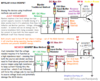
Best to use resistor dividers as voltage dividers - to float DC values of Gate voltages to a threshold level to keep the PART off but allow it to turn on without cutoff issues - and try to keep DC - just plain - DC and Keep RF out of them...
Just don't use so much resistance from the 8 volt sources that the SSB words are "Cutoff" - meaning you aren't in the Gates' Sweet Spot to operate as almost linearly - just off - not totally on. Cutoff is caused by lack of voltage to push the MOSFET on - because only part of the words are getting amplified - you need to increase the bias voltage to a higher level. To do that - lower the FEEDER (your resistor from the +8volt source) resistance to a lower range.
Yes, they do require current to operate - but far less in values than Bipolars. They need voltage to form a field in the Gate to make the device turn on...that requires some current - but not much.
Too much current can cause latching as well as cutoff because there is simply too much power flowing THRU the circuit - so keep the resistance high, to keep the power flow from WASHING AWAY or SWAMPING the RF so it can't get to the Gate...
So, the Graphics above are ARBITRARY - meaning they are not cast in stone...you can use other values like even what the UNIDEN 687 uses in the 520 series they use and have - only it's 8.2K and 4.7K - but that gives you only so much...
Ok to complete this because of time and effort and family life juggling together...
The Self-bias parts - like shown above - the EN1230 / EN369 variants are up to you - they most are for FM or AM work...
But when you want more reliable biasing, you'll have to use sourcing voltages from the on-board regulation system the radio has whether it'd be for the PLL system or the standard 8+volting system - either way, you should bias accordingly but use trimmers too. Not all MOSFET are going to respond in like fashion...
You can find more out about that here - Palomar ERF-2030+ at this link - it's just that time is an enemy of me too, and it sometimes gets in the way. So again I add, that to apply the "divider" is a better option, just not the best for handling variations of signal, voltage, power and other needs of the MOSFET's you decide to drop in there to replace that old worn out Couch of a Final called '2078, or the Refrigerator like the '2312 or the Off-White Kelvinatror - the '1969.
So variations will occur, your mileage may vary, and so therefore add in some trimmers whether on the source side of the feeder line for your voltages, or incorporate the variable in your bias design in the shunt or ground side of the divider - just use a resistor in series with it too to lessen the likelihood of having a bigger failure cause by excessive drive blowing up your variable pot - to pot. So if you blow the Gate, you've applied too much either power or RF drive - more than likely it was from setting idle bias too high and the thing latched on due to the Gate telling the part to turn on. Even when there is no signal. So the Series approach to this helps in getting the Bias current to voltage ratio set properly and low enough to keep the part from latching on by accident or strong RF proximity you didn't plan for.
I'm sure people on here have seen this...
Even this...
Best to use resistor dividers as voltage dividers - to float DC values of Gate voltages to a threshold level to keep the PART off but allow it to turn on without cutoff issues - and try to keep DC - just plain - DC and Keep RF out of them...
NEWLY REVISED

Just don't use so much resistance from the 8 volt sources that the SSB words are "Cutoff" - meaning you aren't in the Gates' Sweet Spot to operate as almost linearly - just off - not totally on. Cutoff is caused by lack of voltage to push the MOSFET on - because only part of the words are getting amplified - you need to increase the bias voltage to a higher level. To do that - lower the FEEDER (your resistor from the +8volt source) resistance to a lower range.
- Above: Note the RESISTOR/BEAD RF Isolation section that is for keeping RF out and allowing some linear bleed of current and power into thru and back out of the bias circuit from the RF input going to the GATE. A simple 50 to 100 ohm resistor of 1/4W value carbon Composition can work as your buffer resistor. You just don't want RF leaking into the bias circuit more that it needs to be - so use the RESISTOR/BEAD combination as much as possible to keep RF where it belongs - at the Gate!
Yes, they do require current to operate - but far less in values than Bipolars. They need voltage to form a field in the Gate to make the device turn on...that requires some current - but not much.
Too much current can cause latching as well as cutoff because there is simply too much power flowing THRU the circuit - so keep the resistance high, to keep the power flow from WASHING AWAY or SWAMPING the RF so it can't get to the Gate...
So, the Graphics above are ARBITRARY - meaning they are not cast in stone...you can use other values like even what the UNIDEN 687 uses in the 520 series they use and have - only it's 8.2K and 4.7K - but that gives you only so much...
Ok to complete this because of time and effort and family life juggling together...
The Self-bias parts - like shown above - the EN1230 / EN369 variants are up to you - they most are for FM or AM work...
But when you want more reliable biasing, you'll have to use sourcing voltages from the on-board regulation system the radio has whether it'd be for the PLL system or the standard 8+volting system - either way, you should bias accordingly but use trimmers too. Not all MOSFET are going to respond in like fashion...
You can find more out about that here - Palomar ERF-2030+ at this link - it's just that time is an enemy of me too, and it sometimes gets in the way. So again I add, that to apply the "divider" is a better option, just not the best for handling variations of signal, voltage, power and other needs of the MOSFET's you decide to drop in there to replace that old worn out Couch of a Final called '2078, or the Refrigerator like the '2312 or the Off-White Kelvinatror - the '1969.
So variations will occur, your mileage may vary, and so therefore add in some trimmers whether on the source side of the feeder line for your voltages, or incorporate the variable in your bias design in the shunt or ground side of the divider - just use a resistor in series with it too to lessen the likelihood of having a bigger failure cause by excessive drive blowing up your variable pot - to pot. So if you blow the Gate, you've applied too much either power or RF drive - more than likely it was from setting idle bias too high and the thing latched on due to the Gate telling the part to turn on. Even when there is no signal. So the Series approach to this helps in getting the Bias current to voltage ratio set properly and low enough to keep the part from latching on by accident or strong RF proximity you didn't plan for.
Attachments
Last edited:
Andy's a hard act to follow.
The one detail he left out that helps explain why a "one size fits all" solution won't work.
Using a fixed resistor would be easier, but the variation from one MOSFET to the next is what makes it necessary to adjust the radio's bias voltage to the final.
The behaviour of a MOSFET when you put enough voltage on the gate to "turn on" the thing is very abrupt.
A tenth of a Volt up or down can throw the MOSFET from a safe level of idle current to either "off", where it won't draw idle current at all.
-OR-
It could cause the transistor to pull a dangerous level of current with no drive power, and overheat it.
A tenth of a Volt doesn't sound like much. The turn-on threshold voltage will vary from one brand of MOSFET to the next, by as much as two or three tenths of a Volt. And individual parts from a batch of 100 can vary by a tenth of a Volt or more. Every batch we buy gets hooked to the tester, and the last digits of the Vth reading marked on the rear of the part with a Sharpie marker. A matched pair or set of four will then be two (or four) parts with the same or nearly-same test marking.
A fixed resistor will never be right for every transistor. The older SSB radios built before the MOSFETs nearly all had a trimmer pot for setting idle-current bias.
AM-only radios depend on DC voltage rectified from the driver transistor's RF input to the final. When there's no drive, the MOSFET is turned off.
SSB is different. No carrier. The driver and final have to be switched on when the mike is keyed, and that means using the radio's switched transmit voltage to provide that DC gate-bias voltage and turn them on before you say "hello".
73
There is another angle being left out of this discussion, at least concerning base-station radios.
The power supply. A MOSFET final will draw more current than the original type. That current has to some from somewhere. And the built-in DC supply probably isn't that large.
An external DC supply will probably be needed if the final is converted to a MOSFET.
73
The power supply. A MOSFET final will draw more current than the original type. That current has to some from somewhere. And the built-in DC supply probably isn't that large.
An external DC supply will probably be needed if the final is converted to a MOSFET.
73
Another problem that should be noted is the mode switch on the base station radios. This component tends to be the bottleneck.
On most base stations, the power the the finals gets routed through the mode switch. Because of this, when modifying a base to run a MOSFET, you can damage the mode switch and cause failure due to excessive current draw from the MOSFET in SSB. I had this issue happen on a Cobra 142GTL. Installed the MOSFET, set the bias voltage at the gate, made sure everything was proper, and the radio was doing in excess of 30W PEP on SSB.
Then, *poof*.
No output.
But only in LSB. I put two and two together and realized, that during testing, I had been using LSB to perform my tests, and had damaged the mode selector switch to the point that the contacts on the LSB portion of the switch had burned open, and the switch was no longer usable.
I replaced the mode switch with a beefier switch, and all was well again. But it should be noted that the stock switch CAN potentially fail if you install a MOSFET, unless you adjust the ALC back so the radio puts out lower power.
Also, Kop is 100% correct, it's probably not recommended to run a fixed value resistor unless the proper value is determined first. Even so, it's best to leave a trimmer potentiometer in its place in the event the MOSFET fails.
~Cheers~
Hey guys!
You came in at a great time, because I too was re-working older sections of the old Galaxy EPT 3600 series boards.
What I found, work with others on, and instructed to do, was to find solutions regarding how to overlay a Gate bias scheme that required voltage more than current - and in doing so, I had to re-work some of my older notes that I had used but were not truly effective unless you added more understanding to the effort.
One of the many problems with Galaxys' older board was the layout and parts placement, So I had to scramble to see why RFX and well as EKL and the IRF upgrades were not always 100% successful.
What I've found was you need to rethink the bias circuit from a low-impedance high-current path to keep the Base just ready to turn on - using more current than a voltage.
MOSFET are different so with this extra time I have had these past few weeks I went back and reworked some of my graphics to show these newer changes that are there - in other designs - so I don't want to get into a debate over intellectual property rights, but if you can see how these concepts are applied you can then take this ball and run with it yourself.
One of the main ones, was the REQUIRED use of a 100K trimmer pot on the older Galaxy design. OR in some later models - they used lower values of 50K or even 10K as a method to provide more current flow to maintain the bias threshold.
Well, I had, and have to find answers even now, as to the way to address it.
We need to think more along the lines of SERIES for MOSFET versus the PARALLELED designs for BIPOLAR we can still use diodes for thermal as well as intrinsic holdovers from the days of regulation and means of providing a cushion or inherent voltage "stay" (best word for this at the moment - REGULATION doesn't seem to fit) to keep the MOSFET gate from not working correctly as we try to provide amplification for lower and lower levels of power and yet keep linearity.
I reworked one graphic to this in hopes that others can understand what I've learned in the past few years of having to un-do that which was done, to re-do to the correct and then figure out from that what is actually wrong with the design.
So don't get mad, but I am glad this came up for I had to reapply all my notes into pared sown graphics I hope others may understand.
See below, it is some of my work but added and modified...

What I've been seeing in the Amateur as well as later generations of Uniden and Cobra are the ABSENSE of the Bi-polar transistor and now they're using everything in MOSFET they can get their hands on.
So they have to scramble as well and come up with the most used design of the century and that is the voltage divider circuit - not for current - but for the 1/2 level of voltage these MOSFETS need to drive.
What makes the idea suck though, is the LACK of current and power the simple divider can provide in keeping up with the demands the Gate needs. The Gate itself takes everything and modifies in in such a way that the DC level itself is used up. It's truly a black box approach but to me this works because I've simply gone SERIES instead of paralleled in the resistor.
But too, look at the DIODE ones, I've seen a "clipper" design that's pretty wild. See Figure 2 - A ZENER is used in this as a clipper it gets power from the RF signal much like a EN369 device, but in using this, when your signal has gone beyond a set level of NEGATIVE swing, you can damage the Gate - so they use a Zener to tap into a 8 volt regulated line to handle a negative going RF wave signal because of the way the Zener is oriented in the circuit - If more power is needed for the effort to pass a high-power - read wide dynamic signal - that Zener can operate as a clipper or crowbar to obtain more DC power to be applied to the Gate.- I've never seen Zeners used like that before. There's more support in that design, but again intellectual property rights apply so I'm just giving generalized ideas for the concepts.
Figure 3 I've seen more of and like to see used more, but the variants of that design also are widely configured and so the parts you may have used are done at your discretion. But the CONCEPT that Figure 3 uses, as a true means to hold back or raise a voltage from the DC bias from a resistive level onto an intrinsic trait of PN junctions is about the best I've seen so far. It goes back to the "Mauldulator design" of old. where the 4558 chips feedback circuit is replaced with a set of diodes and resistors tied parallel and series together so they conduct like a set resistor both ways, but when the feedback loop is increased, by demand of output from the output pin is placed back thru it - diodes are also arranged in a fashion as to conduct very well in one way - that changes the dynamics of the circuit from a simple feedback resistive loop onto a clipping function because now the diodes conduct to overcome the resistive effects of the series resistance set - and the diodes then form a on-way direction path to handle the feedback - as a compressor/clipper function.
Some of you may remember this - from a Maulduator thread in CB Tricks nearly a decade ago...

This design and compare it to the Trio Diode design of the Bias circuit - you can see how this concept can favor those drive levels that use wide dynamic range - much like an ASYMOD so to speak.
So if you feel the need to flame or flambé' me - relook over the above, for in each scenario, I'm talking divider, and used with a trimmer to make this an adjustable means. What I posted in the graphics post above, is how so may other designs simply perform a "plug in this to make this work like that" -type of scenario - it's frustrating...
So yes, Ranger may be mad because Bennie may cost them money. He didn't start it, nor did he even do anything to implicate himself - but they HAVE A RIGHT TO blame him for allowing their own words to be used against them when it comes to warranty work and open frame architecture? How soon do they forget to remember - THAT they bought Galaxy and all it's inherited faults. So to me, this just simply means they're tired of fixing older radio platforms and would rather get out of the business overall and let the rest of us fend for ourselves. Nice thinking Ranger guys, this what you leave us to believe...SIGH...we're trying to help you.
Now why did I say the above? Well, CB Tricks may be gone forever, but GOSH DARN IT, I'm Still Here! and was just as much of a Victim of it as anyone else - we lost a lot from losing the Forum database - but to keep what little I have of it - seems like a lot - but it is not enough compared to the joy of knowing all those that made we WANT to log back in as soon as I could get off the truck and into a terminal that had Wi-Fi I could use. I had fun learning - and made mistakes too - but overall it was a blast - sad to see it come to this though...
You came in at a great time, because I too was re-working older sections of the old Galaxy EPT 3600 series boards.
What I found, work with others on, and instructed to do, was to find solutions regarding how to overlay a Gate bias scheme that required voltage more than current - and in doing so, I had to re-work some of my older notes that I had used but were not truly effective unless you added more understanding to the effort.
One of the many problems with Galaxys' older board was the layout and parts placement, So I had to scramble to see why RFX and well as EKL and the IRF upgrades were not always 100% successful.
What I've found was you need to rethink the bias circuit from a low-impedance high-current path to keep the Base just ready to turn on - using more current than a voltage.
MOSFET are different so with this extra time I have had these past few weeks I went back and reworked some of my graphics to show these newer changes that are there - in other designs - so I don't want to get into a debate over intellectual property rights, but if you can see how these concepts are applied you can then take this ball and run with it yourself.
One of the main ones, was the REQUIRED use of a 100K trimmer pot on the older Galaxy design. OR in some later models - they used lower values of 50K or even 10K as a method to provide more current flow to maintain the bias threshold.
Well, I had, and have to find answers even now, as to the way to address it.
We need to think more along the lines of SERIES for MOSFET versus the PARALLELED designs for BIPOLAR we can still use diodes for thermal as well as intrinsic holdovers from the days of regulation and means of providing a cushion or inherent voltage "stay" (best word for this at the moment - REGULATION doesn't seem to fit) to keep the MOSFET gate from not working correctly as we try to provide amplification for lower and lower levels of power and yet keep linearity.
I reworked one graphic to this in hopes that others can understand what I've learned in the past few years of having to un-do that which was done, to re-do to the correct and then figure out from that what is actually wrong with the design.
So don't get mad, but I am glad this came up for I had to reapply all my notes into pared sown graphics I hope others may understand.
See below, it is some of my work but added and modified...
What I've been seeing in the Amateur as well as later generations of Uniden and Cobra are the ABSENSE of the Bi-polar transistor and now they're using everything in MOSFET they can get their hands on.
So they have to scramble as well and come up with the most used design of the century and that is the voltage divider circuit - not for current - but for the 1/2 level of voltage these MOSFETS need to drive.
What makes the idea suck though, is the LACK of current and power the simple divider can provide in keeping up with the demands the Gate needs. The Gate itself takes everything and modifies in in such a way that the DC level itself is used up. It's truly a black box approach but to me this works because I've simply gone SERIES instead of paralleled in the resistor.
But too, look at the DIODE ones, I've seen a "clipper" design that's pretty wild. See Figure 2 - A ZENER is used in this as a clipper it gets power from the RF signal much like a EN369 device, but in using this, when your signal has gone beyond a set level of NEGATIVE swing, you can damage the Gate - so they use a Zener to tap into a 8 volt regulated line to handle a negative going RF wave signal because of the way the Zener is oriented in the circuit - If more power is needed for the effort to pass a high-power - read wide dynamic signal - that Zener can operate as a clipper or crowbar to obtain more DC power to be applied to the Gate.- I've never seen Zeners used like that before. There's more support in that design, but again intellectual property rights apply so I'm just giving generalized ideas for the concepts.
Figure 3 I've seen more of and like to see used more, but the variants of that design also are widely configured and so the parts you may have used are done at your discretion. But the CONCEPT that Figure 3 uses, as a true means to hold back or raise a voltage from the DC bias from a resistive level onto an intrinsic trait of PN junctions is about the best I've seen so far. It goes back to the "Mauldulator design" of old. where the 4558 chips feedback circuit is replaced with a set of diodes and resistors tied parallel and series together so they conduct like a set resistor both ways, but when the feedback loop is increased, by demand of output from the output pin is placed back thru it - diodes are also arranged in a fashion as to conduct very well in one way - that changes the dynamics of the circuit from a simple feedback resistive loop onto a clipping function because now the diodes conduct to overcome the resistive effects of the series resistance set - and the diodes then form a on-way direction path to handle the feedback - as a compressor/clipper function.
Some of you may remember this - from a Maulduator thread in CB Tricks nearly a decade ago...
This design and compare it to the Trio Diode design of the Bias circuit - you can see how this concept can favor those drive levels that use wide dynamic range - much like an ASYMOD so to speak.
So if you feel the need to flame or flambé' me - relook over the above, for in each scenario, I'm talking divider, and used with a trimmer to make this an adjustable means. What I posted in the graphics post above, is how so may other designs simply perform a "plug in this to make this work like that" -type of scenario - it's frustrating...
So yes, Ranger may be mad because Bennie may cost them money. He didn't start it, nor did he even do anything to implicate himself - but they HAVE A RIGHT TO blame him for allowing their own words to be used against them when it comes to warranty work and open frame architecture? How soon do they forget to remember - THAT they bought Galaxy and all it's inherited faults. So to me, this just simply means they're tired of fixing older radio platforms and would rather get out of the business overall and let the rest of us fend for ourselves. Nice thinking Ranger guys, this what you leave us to believe...SIGH...we're trying to help you.
Now why did I say the above? Well, CB Tricks may be gone forever, but GOSH DARN IT, I'm Still Here! and was just as much of a Victim of it as anyone else
- we lost a lot from losing the Forum database - but to keep what little I have of it - seems like a lot - but it is not enough compared to the joy of knowing all those that made we WANT to log back in as soon as I could get off the truck and into a terminal that had Wi-Fi I could use. I had fun learning - and made mistakes too - but overall it was a blast - sad to see it come to this though...
Last edited:
well post a pic of the Driver and Final portion of the board and see if we can help.
But right now...
Madison or Washington - they're a lot like the Grant XL and Cobra 148 style of yesteryear. It's re-work will be extensive. IT's not for the nostalgic or feint of heart.
You don't have bias issues like the older versions, so you'll be removing more parts and swapping in less parts from it, So you'll be removing OEM parts and so THAT MEANS to KEEP things IN ORDER, stay ORGANIZED so you can REASSEMBLE the board back to the OEM you're converting...if it don't work out
Get an IRF510 and IRF520 - your IRF 510 becomes your Driver - while the IRF520 becomes your Final. You can use two 520's but not two 510's - so choose wisely - why 510 too? It's the less powered "sister" complementary to the 520 - works a lot like a 2166 - so you should follow hierarchy structure and use Driver and Final parings. Why? Well, if you don't want to re-solder blown traces - or like have to re-work sections that took on too much current - and them you have to continuity check all your work back to find the fault of a blown trace of popped part - then please understand the complexity of the install and respect it.
You'll need several Disc caps of NPO quality - 1500pF or 0.0015uF or 152 Disc. Two of them and one of a value approximately 2200 onto 2700pF (0.0022uF or 222 - onto 0.0027uF or 272 Discs as for your output) to couple to your tank circuit.
You may have most of the caps you need already in place, but remember the Gates of the MOSFETS' require a lot more, larger valued heavy input capacitance (Gate cap values will be pretty large) So the values you have may be too small to achieve the effect.
So you have to make some serious choices - removing of the OEM parts to clear out the section so you can re-populate it is not as simple as it appears - you do this in steps...Best to do the Final first, because you can then verify it's "interface" to the older OEM Driver and get it to output power - before you swap that Driver section out.
But right now...
- I'm not here as a "stand alone tech" that will fix your work as you go on into and run into problems.
- I don't get paid for this...
- This thread is about the experimentation and utilization of the UPGRADE to new MOSFET from the Bi-polar era and it's issues.
- Stop here and find a tech that can work alongside you if you are not comfortable or confident enough to do the work on your own.
- You may be here far longer than all of the ENTIRE population of CB'ers left in the U.S. - that's quite a feat - Congratulations! And No - it still does not allow you to get free passes to Disneyland or Tokens to pay for your commute to and from New Jersey Turnpikes...nor would you even need to ask...because you've seen and been thru this already...
Madison or Washington - they're a lot like the Grant XL and Cobra 148 style of yesteryear. It's re-work will be extensive. IT's not for the nostalgic or feint of heart.
You don't have bias issues like the older versions, so you'll be removing more parts and swapping in less parts from it, So you'll be removing OEM parts and so THAT MEANS to KEEP things IN ORDER, stay ORGANIZED so you can REASSEMBLE the board back to the OEM you're converting...if it don't work out
Get an IRF510 and IRF520 - your IRF 510 becomes your Driver - while the IRF520 becomes your Final. You can use two 520's but not two 510's - so choose wisely - why 510 too? It's the less powered "sister" complementary to the 520 - works a lot like a 2166 - so you should follow hierarchy structure and use Driver and Final parings. Why? Well, if you don't want to re-solder blown traces - or like have to re-work sections that took on too much current - and them you have to continuity check all your work back to find the fault of a blown trace of popped part - then please understand the complexity of the install and respect it.
You'll need several Disc caps of NPO quality - 1500pF or 0.0015uF or 152 Disc. Two of them and one of a value approximately 2200 onto 2700pF (0.0022uF or 222 - onto 0.0027uF or 272 Discs as for your output) to couple to your tank circuit.
You may have most of the caps you need already in place, but remember the Gates of the MOSFETS' require a lot more, larger valued heavy input capacitance (Gate cap values will be pretty large) So the values you have may be too small to achieve the effect.
So you have to make some serious choices - removing of the OEM parts to clear out the section so you can re-populate it is not as simple as it appears - you do this in steps...Best to do the Final first, because you can then verify it's "interface" to the older OEM Driver and get it to output power - before you swap that Driver section out.
Last edited:
Does anyone know the correct way to run mosfets in the President Madison?,
Start with a bigger power supply.
73
A very interesting read! Just wanted to say thank you to all who are working to keep the older radios on the air as inexpensively as possible!
dxChat
- No one is chatting at the moment.
-
-
@ AudioShockwav:Try starting a new thread in the Amplifier section and asking the question, more people will see it to respond.
-
-
-