I would be happy to provide pictures and the way I tune them up. Email me at tiny@tinyscbshop.com. The npc\rc modification and tune is similar to the ranger boards. Be forewarned that the proper mod is with a one end 9:14 or 1 in 4148 signal tired and a 100 ohm 2-watt resistor. While the mod can be done with only the diode for a higher yield in average Watts, I have it installed with a competition quad six that I can switch the mod in and out of the circuit.the radio is easily capable of producing pep wattage in excess of 100 Watts. I drive my 2 pill class c with the radio and yield close to 430 w. Pep, at 13.8 v. It makes a perfect driver for a class c-2 pill or idling along a 6 or 8 pill.shoot me that email and I'll try to get a response together sometime tomorrow. Long live CB tricks mirror sites! I hope Benny brings it back or whoever took it over. What a fantastic resource it was for the online manuals service manuals etc. A wealth of information that hopefully others downloaded before its demise.

You are using an out of date browser. It may not display this or other websites correctly.
You should upgrade or use an alternative browser.
You should upgrade or use an alternative browser.
-
You can now help support WorldwideDX when you shop on Amazon at no additional cost to you! Simply follow this Shop on Amazon link first and a portion of any purchase is sent to WorldwideDX to help with site costs.
-
A Winner has been chosen for the 2026 July 4th Retevis RA89R Giveaway! Click Here to see who won!
Anytone at-6666 v3
- Thread starter Eldorado828
- Start date

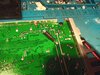
The NPC RC mod is as follows. 1N 4148 signal diode, cathode to center leg of AM regulator. Use a 50 to 100 ohm 1 watt resistor attached to the anode, other end of resistor t0 positive pin of capacitor shown in picture. This is identical to the stryker 955 and stryker 655 n p c r c AKA swing mod. Make sure you are soldering the other end of the resistor to the positive end of the aforementioned capacitor which is closest to the rear of the radio, if you short that capacitor you will not like the results AKA lots of smoke. Be careful as the pins of the capacitor are extremely close together. Use shrink tubing. Now you'll have full carrier development from any dead key. EnjoyCan you give us any info on the npc/rc? I have a 5555 and think it rivals my 955 and only half the cost.
Attachments

Last edited:
I believe the only reason people would tell you to swap out the mosfets for different ones are because they were running it with the 20 watt dead key out of the box. Foolish of anytone and striker to have out-of-the-box dead keys that high. I recommend no more than a 7 watt dead key on maximum power. Half a watt on low-power. NPC slash swing mod is as follows, 1n 4148 signal diode cathode to center Leg of AM regulator. Anode to a 50 ohm 1 watt resistor or hundred watt resistor. Other end of resistor to positive pin of a capacitor. The positive pin is closest to the rear of the radio as pictured. Be very careful not to short to the ground otherwise you will smoke the PA stage. Full swing from a half a watt dead key to full dead key. Enjoy. P.S. keep that dead key on high power below 8 watts! If you maintain a high-wattage carrier you're going to heat up the mosfets and end up frying them. Keeping the high power dead key at 7 Watts and I've never had one of these radios come back with blown finals.What would you replace the finals for and to which ones. If you're talking about the 2030+ believe they are overrated for what they are. The radio with either the 520's or 13n10's does exactly what it was designed to do and does really well as is. That's just my take on it
Attachments

Last edited:
the NPC / swing mod will work for the anytone quad 6, Stryker 955, Stryker 655, the anytone quad 5 and quad 5 end, it's all the same circuit. Cathode of 1N4148 signal diode to center pin of the a.m. regulator. I add a 47 ohm 2 watt resistor for slightly more peak, you can use up to a hundred ohm or more if you want to tighten the peak a bit. Solder the resistor to the anode and the other end of the resistor as pictured to the rear most solder joint which is the positive pin of a capacitor. Do not short the two or you will fry the PA stage. Heat shrink it and enjoy.Can you give us any info on the npc/rc? I have a 5555 and think it rivals my 955 and only half the cost.
Attachments
Hi shadetree, Anytone 5 5 5 5 and 5555 n both have pretty much the same identical PA stage. It is a one driving two mosfet p a stage. The swing Mod mentioned previously will also work with the quad 5 radio. I own a couple of quad fives and find them to be outstanding radios. To be honest, I've seen a huge decline in build quality from all ranger products and Cobra products, thin circuit boards and continuing issues with cold solder joint right out of the box. I have yet to see a single problem with any of the several anytone models that have come across my bench and the same goes for Stryker. They are simply better made radios and the surface mount does not have near as many problems as through-hole components. I'd be happy to help with any of those radios you'd like to try that mod on.Can you give us any info on the npc/rc? I have a 5555 and think it rivals my 955 and only half the cost.
How can I tell I have version three I just got mine in yesterday they said they got from the factory 2 weeks agoWell fellas, I got a v3 version of the radio in Monday and finally got around to cracking it open to do some quality inspection. So just for future owners I wanted to say this newest batch changed to the vishay irf-520's just like what Ranger uses. No more 13n10's. After checking bias voltages, carrier adjustments and the typical light adjustments it runs just as good as the v2 (with 13n10's) I'm using as a mobile but much cooler. It's about 10 watts less pep but I don't think it'll be noticeable unless you're a meter junkie. I know there are several folks that had blown finals with the previous ones using the n10's and although I haven't ran into that issue only time will tell how these do as far as longevity. When I get free again to tinker with my personal stuff I'll put the older one on the bench to compare and see what else is changed or upgraded in this newer version. Many knock them for being Chinese but I've had a great streak with the anytone bunch so far and I'm a RCI chassis guy by preference. Anyhow, there isn't much info on these rigs out there so I figured I'd share my findings with others on here. Hope everyone has had a blessed start to the new year!
Mine has the 13n10 in it and bands A-J this radio had troubles couldn't find jack crap on it or the info on tuning the TX chain had.to send it out been 2 weeks so far the shop didn't get around to it yet so went and bought a 98vhp.
Hi gents new member here and my first post, so please be gentle.
I have purchased two Q6 radios, one second hand, 3 months old & the other brand new. I put them on the bench to see what they can do power wise, I wanted to "calibrate" the power control so l know what low, mid range & high settings would give RF wise.
Here are my findings.
S/H radio
AM low power setting 24Watts High 30Watts SSB Low 37 Watts High 37 Watts on whistle
New radio
AM Low power setting 1.6Watts high 13.6 Watts SSB Low 4 Watts High 55 Watts
I did a pot comparo with the new one and found the S/H one had most of the pots in the TX path all screwed around, way off mid range setting, as mentioned by others earlier, when ccts are designed the adjustments should lay mid range. So I went through and set all the pots very close to the new radios adjustments. Then carefully peaked TX from there making small adjustments till the power matched the output power of the new radio.
So if you are still with me so far, here is the question.
I hear about bias, how or where do I check to see if I'm in the ballpark or way off field?
I want to open them both up to see what finals I have in both radios, at this stage its unknown.
So far the radios have very good field reports using the stock mic but thinking about upgrading to a power mic, Astatic road devil appears to be the go to mic. Anyones thoughts on that?
Last edited:
Wanted to compliment you on your thinking about how to properly re-set a radio - may not be perfect, but if all else is equal (parts not missing or changed aside from the trimming of the pots) you should be ok.
Sorry to know that you have to purchase an original and use it to help re-align your Second Hand radio - don't worry. With Radios and their complexity these days, if you can just get the thing to work like the original one next to it - is a feat in itself...The lack of documentation from "overseas" has made alignments and repairs of these radios' difficult for even the experienced techs.
You asked about Finals - they did away with Bi-polar and are now using- LD-MOS Linear Device - MOS - FET designs - making them more like their Bipolar counterparts in power curve but less ohmic losses incurred thru their junctions - for they did away with the "direct PN" junction interaction that makes the Bi-polar a current muncher, with the Voltage Driven "Field Proximity" effects taking over, as the way to switch these on or off - they do a pretty good job of being faithful in providing output from the original input signal.
In the newer radios - they are doing away with "bias pots" and going with pre-set values.
The only problem with that is the drop in replacements are going to have a different bias trigger voltage even in tenths of a volt...
So yes, the replacements may need to be exact to the number, you should not mix IRF520 and 13N10s' or something exotic - into whatever they are using - they need to be identical in numbering assignment to at least be triggered "properly" and exhibit the right power curve to stay stock and original tuning like you wanted.
So you need to operate the radio within it's original set parameters (your re-alignment using a another OEM one as a template can help immensely in this...) else if you blow a Final - you may have to replace not just the bad final - but the ENTIRE strip. Why? Because the "lots" purchased by the manufacturer have made them pre-set their radios bias' levels for that particular MOSFET design. While you - being in the field and needing a replacement asap - may be out of luck in getting the OEM back out of the radio unless you are willing to delve and dive into the quandary of BIAS proper settings and drive levels per stage to restore the radio back to OEM operation.
The AT-6666 runs the Mic it has wired up for it to enable features and is programmed for it - if you need a replacement mic for it - unless you are willing to lose a lot of features and can tolerate the audio audible differences the filtering the radio uses - it is set up specifically for their mics, not power mics.- remember that the connector pins need to go somewhere - so be aware that to even make it key up - you may need to take it to a shop unless you're comfortable with how the manual shows you what to wire to where and do it yourself...
Sorry to know that you have to purchase an original and use it to help re-align your Second Hand radio - don't worry. With Radios and their complexity these days, if you can just get the thing to work like the original one next to it - is a feat in itself...The lack of documentation from "overseas" has made alignments and repairs of these radios' difficult for even the experienced techs.
You asked about Finals - they did away with Bi-polar and are now using- LD-MOS Linear Device - MOS - FET designs - making them more like their Bipolar counterparts in power curve but less ohmic losses incurred thru their junctions - for they did away with the "direct PN" junction interaction that makes the Bi-polar a current muncher, with the Voltage Driven "Field Proximity" effects taking over, as the way to switch these on or off - they do a pretty good job of being faithful in providing output from the original input signal.
In the newer radios - they are doing away with "bias pots" and going with pre-set values.
The only problem with that is the drop in replacements are going to have a different bias trigger voltage even in tenths of a volt...
- which can make big differences in how the radio with work
- - staying "in stock operation (fine)"
- Being - Good to go...
- - or go off on a tangent and either "latch up" until it blows up the replacement final...
- - or work more like a Kraco Emergency Channel 9 HELP radio from the late 80's - getting you nowhere...
- (both bad)
So yes, the replacements may need to be exact to the number, you should not mix IRF520 and 13N10s' or something exotic - into whatever they are using - they need to be identical in numbering assignment to at least be triggered "properly" and exhibit the right power curve to stay stock and original tuning like you wanted.
So you need to operate the radio within it's original set parameters (your re-alignment using a another OEM one as a template can help immensely in this...) else if you blow a Final - you may have to replace not just the bad final - but the ENTIRE strip. Why? Because the "lots" purchased by the manufacturer have made them pre-set their radios bias' levels for that particular MOSFET design. While you - being in the field and needing a replacement asap - may be out of luck in getting the OEM back out of the radio unless you are willing to delve and dive into the quandary of BIAS proper settings and drive levels per stage to restore the radio back to OEM operation.
The AT-6666 runs the Mic it has wired up for it to enable features and is programmed for it - if you need a replacement mic for it - unless you are willing to lose a lot of features and can tolerate the audio audible differences the filtering the radio uses - it is set up specifically for their mics, not power mics.- remember that the connector pins need to go somewhere - so be aware that to even make it key up - you may need to take it to a shop unless you're comfortable with how the manual shows you what to wire to where and do it yourself...
Thankyou for the thought out reply, H A, I appreciate your time. I'll need to re-read it a couple more times to digest it fully but Thank you for the complement.
In a nutshell, the power its producing is more than enough for my requirements and I run it at much less, the max here is 12watts PEP on SSB so hopefully I wont be needing to change any final stages any time soon if at all. Note made, if I do, all 4 need to be changed like for like, understood.
Talking about final stages I did see a YouTube video today of a guy running constant PTT on a Q6 with no antenna, VSWR of 14 or 15 for 2 mins to see if it would blow. It didnt but got very very hot. Anyone see this act? I was cringing for the full 120 seconds.
I'll keep the stock mic") advice taken.
advice taken.
In a nutshell, the power its producing is more than enough for my requirements and I run it at much less, the max here is 12watts PEP on SSB so hopefully I wont be needing to change any final stages any time soon if at all. Note made, if I do, all 4 need to be changed like for like, understood.
Talking about final stages I did see a YouTube video today of a guy running constant PTT on a Q6 with no antenna, VSWR of 14 or 15 for 2 mins to see if it would blow. It didnt but got very very hot. Anyone see this act? I was cringing for the full 120 seconds.
I'll keep the stock mic
advice taken.To help you gain a better idea of that concept of no - bias trimmer control - I once did up a review of a Uniden PC-687 Radio - their upgraded replacement to their PC66/68 series - which failed miserably and was only in production for a few years then dropped.
It's also when they introduced a DEDICATED 6-pin NEW connector requirement because they needed something to help sell their Bearcat (Or BEERCAN) Bluetooth handsets - 906. - the old 4 pin connector days seem to be gone in Unidens book.
Heres' a photo of the Final from that review effort...

To get you up to speed on this...
They use a Resistor / Divider network - meaning that they still do the Bias - only they pre-set the level because they find it works the best under all conditions they subject it to - so they feed using 8.2K with a filter cap and the bias is trapped from there and they place a 4.7K resistor ACROSS the bias line to drop it more than half it's voltage to about 3.0 ~ 3.2 volts. This is a dead giveaway to the type of MOSFET they use - close to the 520's biased threshold turn-on line.
That will work from the IRF-520 - but if you put in a 13N10 or something else like an ERF2030 - that might be TOO much bias voltage and it will latch on and blow because...
NOT OF A BAD SWR, but because it simply turned on with no signal - it turned on because the BIAS line was telling it to turn on - too much voltage.
If the signal was there, and that turned on, with the BIAS set too high, the MOSFET will conduct, yes, but too hard in it's non-linear (nearly full on Digital switch region) ruining the signal and even destroying the part in the process.
If that didn't destroy the part, it will place too much distorted (Spurried) output into a subsequent stage ( Read:Amplifier) and potentially damage that amp.
As you get acquainted with the site, look up some of the 13N10 and IRF520 reviews and Radios like the RCI 2547/Galaxy MOSFET conversion - you'll see where they encountered failures due to poor signal control from overly-volted bias on MOSFET's - even in-between types and Brands.
It's also when they introduced a DEDICATED 6-pin NEW connector requirement because they needed something to help sell their Bearcat (Or BEERCAN) Bluetooth handsets - 906. - the old 4 pin connector days seem to be gone in Unidens book.
Heres' a photo of the Final from that review effort...
To get you up to speed on this...
They use a Resistor / Divider network - meaning that they still do the Bias - only they pre-set the level because they find it works the best under all conditions they subject it to - so they feed using 8.2K with a filter cap and the bias is trapped from there and they place a 4.7K resistor ACROSS the bias line to drop it more than half it's voltage to about 3.0 ~ 3.2 volts. This is a dead giveaway to the type of MOSFET they use - close to the 520's biased threshold turn-on line.
That will work from the IRF-520 - but if you put in a 13N10 or something else like an ERF2030 - that might be TOO much bias voltage and it will latch on and blow because...
NOT OF A BAD SWR, but because it simply turned on with no signal - it turned on because the BIAS line was telling it to turn on - too much voltage.
If the signal was there, and that turned on, with the BIAS set too high, the MOSFET will conduct, yes, but too hard in it's non-linear (nearly full on Digital switch region) ruining the signal and even destroying the part in the process.
If that didn't destroy the part, it will place too much distorted (Spurried) output into a subsequent stage ( Read:Amplifier) and potentially damage that amp.
As you get acquainted with the site, look up some of the 13N10 and IRF520 reviews and Radios like the RCI 2547/Galaxy MOSFET conversion - you'll see where they encountered failures due to poor signal control from overly-volted bias on MOSFET's - even in-between types and Brands.
So if you are still with me so far, here is the question.
I hear about bias, how or where do I check to see if I'm in the ballpark or way off field?
I want to open them both up to see what finals I have in both radios, at this stage its unknown.
To answer your question...
That is how you check/set the bias on the Stryker/Anytone radio.
Got me running circles considering all these radios.
Price (today) seems to be from $220 upwards.
Price (today) seems to be from $220 upwards.
Anyone could share schematic for that radio?
https://simonthewizard.com/2019/01/08/schematic-anytone-at-6666/
dxChat
- No one is chatting at the moment.
