Hmm.
JB2000. Wasn't stored well. Brings to mind the old wisdom "just because you can doesn't mean you should".
But the HV winding on the transformer passed the leakage/breakdown test, and the owner wants it fixed. Several decades of experience working for this guy makes me confident he is serious. Besides, he'll come up with tubes. This one has a bum tube that won't light the filament.
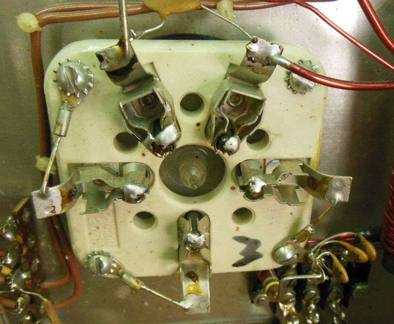
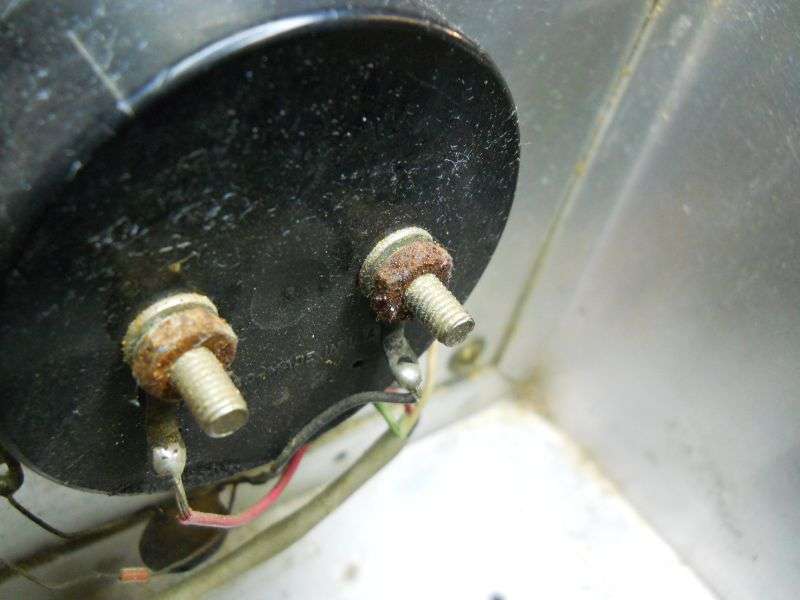
And it's crusty.
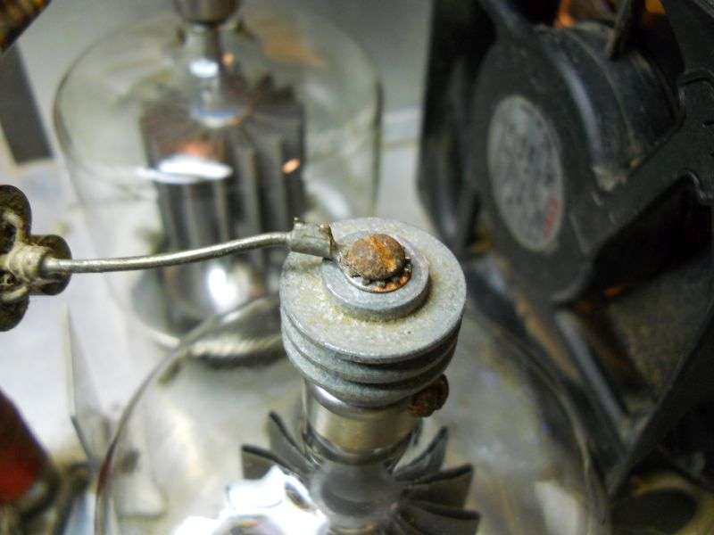
This tube socket is grungy enough the heat from the poor connection is probably what melted the solder from the bad tube's filament pin.
Just don't plug a good tube into a socket that looks like this. It won't be good for long.
Bit by bit the question comes to mind "How many boats did you anchor with this amplifier?"
But wait: There's more.
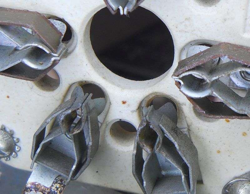
The owner thought this was a low-drive JB. Someone had added a second 8417 driver tube alongside the original socket. But it wasn't hooked up. The drive had been routed directly to the cathodes of the 3-500Z tubes. And the old low-drive input circuit was gone. A big relief, that. Every one of this model we have fixed for decades has been converted to high (direct) drive to the big tubes. The built-in driver is just a bad idea. Never mind why. How do I count the ways?
So the old driver-tube circuit board goes away.
The 12 Volts DC for the antenna relay will come from a rectifier and filter mounted on a tie strip. The keying circuit will be bolted to the rear panel alongside the relay. Not sufficiently interesting to merit a pic.
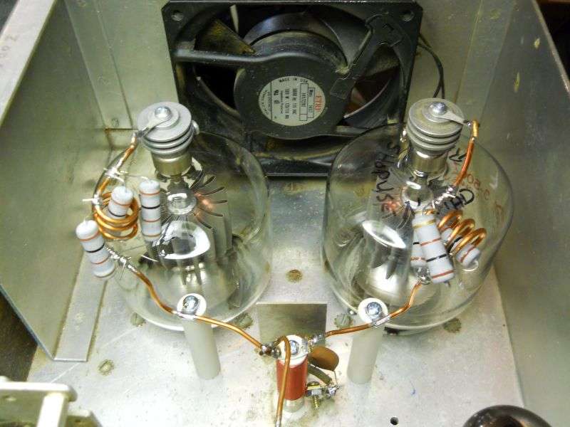
Air conditioner coil cleaner is mostly phosphoric acid, water and blue dye. But soaking the plate caps in it, and a stainless-wire brush got them presentable again.
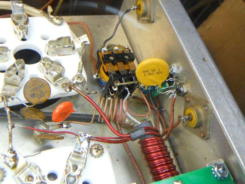
The tubes get a tuned input circuit. The coil is wound on a half-inch form, 68pf to ground on the input side, 27pf to ground on the tube side. The tiny glimpse of green at the bottom of the pic is our diode-bias board, but with only 25 diodes in series. This amplifier runs on 2500 Volts to the plates, so we could use the same HV board that puts a full-wave doubler into a Pride. Not interesting enough for a pic.
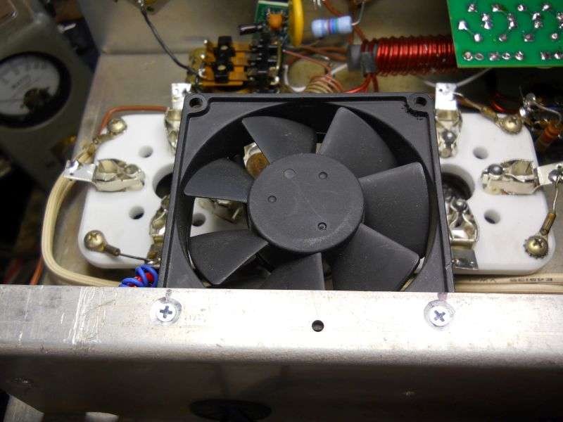
The new tube sockets will last longer with a breeze on the undersides. Doesn't take much. This fan runs from the 12 Volts DC that powers the relay.
The new plate choke is one we make for the Heath SB220, Pride DX300 and others. But it's a bit short compared to the original. The solution is to take two of the ceramic pillars we use to make the choke and anchor the long parasitic-choke leads separately from the choke's connections. Should be more durable when tubes get changed. If I had anchored each parasitic directly to the top of the plate choke, the leverage would have destroyed it before long.
This sure seems like a long post, but I left out a lot. And yes, I did get paid for this job. Anyone who has done this sort of work will have horror stories of orphaned jobs that had good money spent to finish them and never got taken home.
But if you bring me one of these that looks like this one I'll probably make the Dracula sign and tell you not to bother.
73
JB2000. Wasn't stored well. Brings to mind the old wisdom "just because you can doesn't mean you should".
But the HV winding on the transformer passed the leakage/breakdown test, and the owner wants it fixed. Several decades of experience working for this guy makes me confident he is serious. Besides, he'll come up with tubes. This one has a bum tube that won't light the filament.
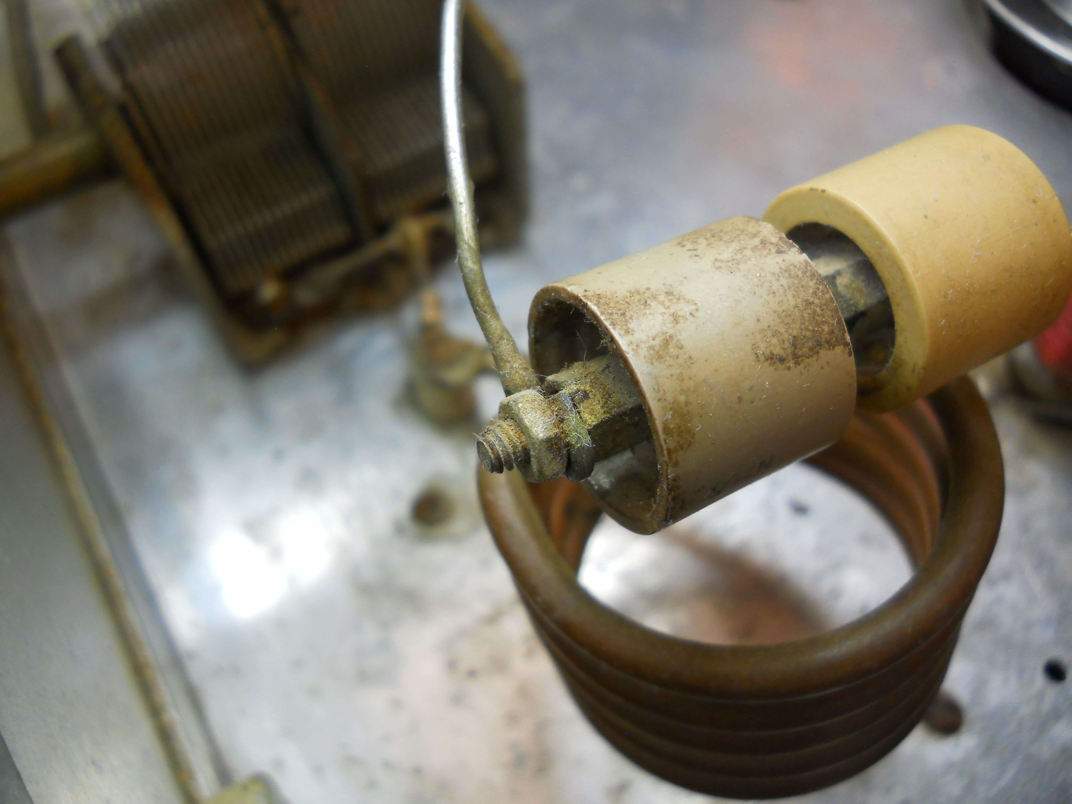
And it's crusty.
This tube socket is grungy enough the heat from the poor connection is probably what melted the solder from the bad tube's filament pin.
Just don't plug a good tube into a socket that looks like this. It won't be good for long.
Bit by bit the question comes to mind "How many boats did you anchor with this amplifier?"
But wait: There's more.
The owner thought this was a low-drive JB. Someone had added a second 8417 driver tube alongside the original socket. But it wasn't hooked up. The drive had been routed directly to the cathodes of the 3-500Z tubes. And the old low-drive input circuit was gone. A big relief, that. Every one of this model we have fixed for decades has been converted to high (direct) drive to the big tubes. The built-in driver is just a bad idea. Never mind why. How do I count the ways?
So the old driver-tube circuit board goes away.
The 12 Volts DC for the antenna relay will come from a rectifier and filter mounted on a tie strip. The keying circuit will be bolted to the rear panel alongside the relay. Not sufficiently interesting to merit a pic.
Air conditioner coil cleaner is mostly phosphoric acid, water and blue dye. But soaking the plate caps in it, and a stainless-wire brush got them presentable again.
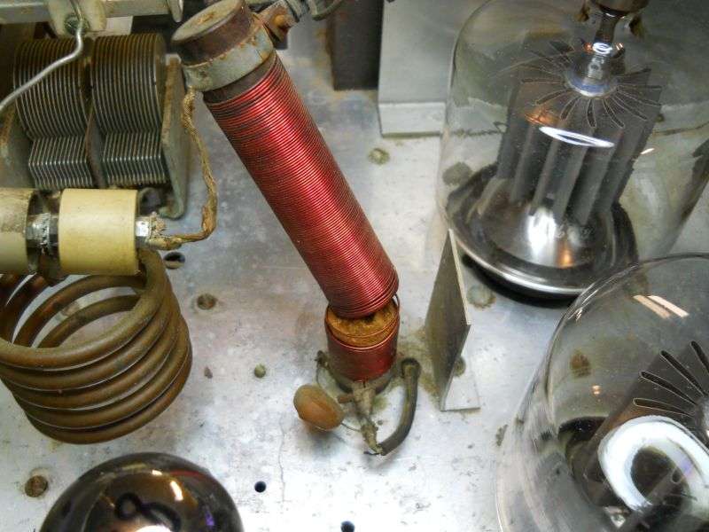
The tubes get a tuned input circuit. The coil is wound on a half-inch form, 68pf to ground on the input side, 27pf to ground on the tube side. The tiny glimpse of green at the bottom of the pic is our diode-bias board, but with only 25 diodes in series. This amplifier runs on 2500 Volts to the plates, so we could use the same HV board that puts a full-wave doubler into a Pride. Not interesting enough for a pic.
The new tube sockets will last longer with a breeze on the undersides. Doesn't take much. This fan runs from the 12 Volts DC that powers the relay.
The new plate choke is one we make for the Heath SB220, Pride DX300 and others. But it's a bit short compared to the original. The solution is to take two of the ceramic pillars we use to make the choke and anchor the long parasitic-choke leads separately from the choke's connections. Should be more durable when tubes get changed. If I had anchored each parasitic directly to the top of the plate choke, the leverage would have destroyed it before long.
This sure seems like a long post, but I left out a lot. And yes, I did get paid for this job. Anyone who has done this sort of work will have horror stories of orphaned jobs that had good money spent to finish them and never got taken home.
But if you bring me one of these that looks like this one I'll probably make the Dracula sign and tell you not to bother.
73