Hey Everyone,
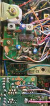
So, I have this Colt-890 from a local op on the bench to see if it can be resurrected. A few things here. I have never worked on a Colt radio before and have never even heard of an 890. This radio is from the late 70’s, still in the original box, has a Cybernet board in it (similar to the Telsat SSB 140) and has above and below 40 from the factory as well as FM. As you can see on the faceplate, the manufacturer must have used this radio for other purposes and just put stickers over some of the functions to change what they do as well as the radio label. I think its super cool!!! The radio has a clarifier that is open (receive only) and a Tune adjustment which adjusts transmit and receive frequency. The tune has a detent and is a course adjustment so it’s not very useful and the Clarifier is fine. It kind of reminds me of an early 80’s President Jackson import. This radio has a lot of factory mods and parts added to the main board. For instance, CT1 on the main board is replaced by a cap and CT2 does not have much of an effect on the alignment. The CT’s on the Band Board seemed to have the most effect.
I was able to get it working by cleaning the controls and switches and fixing the mic. In the end, the mic jack was a 4-pin so I rewired it to a Cobra 4-pin standard. I am still not 100% sure of the alignment as it has some boards in it I have never seen. I have fiddled with it and am able to get it on frequency enough for use but would love any thoughts.
Main Board – PTBM048A0X
Band Board – PT0S012A0X
FM Board – PTZZ050A0X
If anyone has any info on this radio please let me know.