• You can now help support WorldwideDX when you shop on Amazon at no additional cost to you! Simply follow this Shop on Amazon link first and a portion of any purchase is sent to WorldwideDX to help with site costs.
  • A Winner has been chosen for the 2026 July 4th Retevis RA89R Giveaway! Click Here to see who won!

cobra 25 ltd classic st/mosfet

Thank you for the chart and information! Great read. I was only thinking that it might be cool to have a radio with no Amp go double the distance as a stock radio.

 
doubling your power is good for about maybe 1/2 s unit on the other end, not so much for increasing range. a final swap is more for propery driving certain amps with a high swing from a low DK.
 
  • Like
Reactions: loosecannon
Yes only 1/2 s unit. I was thinking about two FETs as the final. I get 8 watts carrier and swing to 40 watts at like 16.5 volts. So my thought was to use dual fets and get a 16 watts carrier which according to the chart I read would double distance from a stock 4 watts radio. But I get stoned alot and have silly radio thoughts. Usually not practical thoughts at that.
 
i think if you want to do dual final mods, galaxy is the brand you want if you can find one cheap somewhere in the wild. they leave the area wide open. i dont see an easy way to do duals on a 25 unless you are making a stinger
 
looking for info on how to do the IRF520 mosfet upgrade to a cobra 25ltd classic st. need info on the parts and the installation. and what i should expect on the output after the installation. then i'm gonna do the swing kit utilizing the cap and the resistor. gonna set it up to use it with a killerbee 250hd linear
looking for info on how to do the IRF520 mosfet upgrade to a cobra 25ltd classic st. need info on the parts and the installation. and what i should expect on the output after the installation. then i'm gonna do the swing kit utilizing the cap and the resistor. gonna set it up to use it with a killerbee 250hd linear. thank you.
Hi if I change the final to a mosfet.. Shouldn't I also chang the driver to a mosfet?
 
i find doing the TIP120 var dk with a mosfet, i find that putting a 4.7k from the +8v switched tx line makes it all play nice together. the class C setup on the FET depends on the carrier to work. i have a 66xl and i can clean swing from 20mw to 25w
I'm hoping you can help me troubleshoot a mosfet install in a Uniden PC68XL. Swapped the driver for a 2166 and installed a Vishay520 mosfet with the Pal-EN1230-Kit (fixed bias) as instructed in the R40 resistor through hole(s). Gate v is .3 when keyed.
 
Did you put the 1230 in the correct way? If backwards, it won't generate + bias.

edit: And why in the world would those instructions say to remove the static discharge resistor R38? because its only rated for half a watt. Put a quarter watt 10k there.
 
Last edited:
Did you put the 1230 in the correct way? If backwards, it won't generate + bias.

edit: And why in the world would those instructions say to remove the static discharge resistor R38? because its only rated for half a watt. Put a quarter watt 10k there.
To the best of my understanding. I combined the PAl-EN1230 diagram with the Web instructions for swapping out R40. What baffled me was the "kit" has the diode band facing the + leg and the web instructions have the R40 + leg facing L12. Doesn't seem logical to me, but I'm new to this.

My understanding was that the band should be facing the input of the V. Though I followed the instructions to a T.

After messaging the vendor of the "kit" they seemed to think the 2166 was the issue. IDK. My understating was upgrading the driver was a + for hitting the Vishay 520 with more juice.

I have a pre China Cobra 29 that I would like to upgrade, but don't trust the web instructions now!
 
That is correct, the + leg must be towards L12. It acts as a detector to raise the DC bias point.

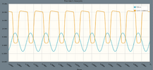
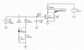
I threw together an example. It may not model exactly like the radio, but it illustrates what happens. The diode rectifies some of the driver signal and adds that DC to the waveform going to the mosfet gate. As the DC increases, more of the incoming waveform is turning on the mosfet (mosfet turns on above 3.5v, give or take .5v).
1784047262947.png
1784047314390.png
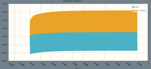
and after it settles, this is what it looks like zoomed in
1784047365490.png
If the diode was backwards, this blue driver waveform would not climb up.

I am not saying the instructions are wrong as I have never done one of those, but when I model this with C149 and C46 as they are in the schematic, I don't get any DC. It needs more drive. I removed the shunt cap (reduced it to 1pF in the sim) and changed the 270p to 680p and thats how I got this waveform.

Again, this is just a rough incomplete circuit model, your scope readings may vary. Mainly did this just to illustrate what that diode is doing.
 
  • Like
Reactions: Cable Guy
That is correct, the + leg must be towards L12. It acts as a detector to raise the DC bias point.

I threw together an example. It may not model exactly like the radio, but it illustrates what happens. The diode rectifies some of the driver signal and adds that DC to the waveform going to the mosfet gate. As the DC increases, more of the incoming waveform is turning on the mosfet (mosfet turns on above 3.5v, give or take .5v).
View attachment 77363
View attachment 77364
and after it settles, this is what it looks like zoomed in
View attachment 77365
If the diode was backwards, this blue driver waveform would not climb up.

I am not saying the instructions are wrong as I have never done one of those, but when I model this with C149 and C46 as they are in the schematic, I don't get any DC. It needs more drive. I removed the shunt cap (reduced it to 1pF in the sim) and changed the 270p to 680p and thats how I got this waveform.

Again, this is just a rough incomplete circuit model, your scope readings may vary. Mainly did this just to illustrate what that diode is doing.
Thanks, you cleared things up.

The kit was installed with the diode and resistor configuration, as shown, but...

The instructions state to install the bias kit in the R40 through holes. I see that your diagram connects the bias to L12. After looking at the instructions a second time, it sates to install the + "towards L12." It wasn't clear to me that they shared a trace. Yet the bias kit + went in the R40 hole nearest L12.

73's!
 
Last edited:
I just took a look at this "mod."
hmmm, wonder how many actually got it to work. ?

with the driver TR8 changed to a 2166 -

maybe not enough RF drive to TR8, so tune up L14.
and L13 for maximum to drive TR7.
and L10 for output level.

so watch the RF output on the meter, and tune up,
starting at L14, then L13. L10. maybe go back and forth a little.

if this does not work, put the original TR8 back in.

TR8 feeding TR7 is a no-bias class-C (maybe E) RF amp circuit.
it would be nice to have well over +5 volts peak at gate
of that added MOSFET. at 27 MHz this can be a problem.

on my little AM transmitters, I build, but at 4.915 MHz,
where it is easy, I drive an IRF510 MOSFET with an
almost square-wave going from zero to 11 volts.
15 watts carrier continuous.
you can find it on YouTube @RadioPhreak

....
 
I have read online that the IRF520 and the ERF-2030 are NOT the same transistor. When I got my IRF520's from mouser, they all have a gate capacitance of about 680pF. I am going to guess that the ERF-2030 had far less.

When I first modeled this, I used the values the schematic showed. The mod sheet did not talk about removing C149. It didn't drive the 520 at all. I made the assumption that the IRF520's capacitance was so high that C149 did not have to be there. When I removed it in the sim (turned it into 1pF so I didn't have to delete the component), I noticed I was now getting drive to the 520. However, it wasn't enough, so I then raised that C46 to 680pF to let more through and I was getting good results.

I don't think there is anything wrong with your parts or installation, I simply think the IRF520 requires far more drive than the 2030 due to its gate capacitance. This is, of course, pure speculation. If you are up for experimenting, I would completely remove C149 and slowly increase C46 until the negative peaks can't go any lower (which is not going to be exactly 0v, maybe closer to 1v). If my suggestion costs you a 520 or two, let me know. I have about 80 of them and would happily drop a couple in the mail to see if this works.

edit: the matching network may need adjusting too, but thats a different battle
 

dxChat
Help Users
  • No one is chatting at the moment.