
Thank you for the chart and information! Great read. I was only thinking that it might be cool to have a radio with no Amp go double the distance as a stock radio.


looking for info on how to do the IRF520 mosfet upgrade to a cobra 25ltd classic st. need info on the parts and the installation. and what i should expect on the output after the installation. then i'm gonna do the swing kit utilizing the cap and the resistor. gonna set it up to use it with a killerbee 250hd linear
Hi if I change the final to a mosfet.. Shouldn't I also chang the driver to a mosfet?looking for info on how to do the IRF520 mosfet upgrade to a cobra 25ltd classic st. need info on the parts and the installation. and what i should expect on the output after the installation. then i'm gonna do the swing kit utilizing the cap and the resistor. gonna set it up to use it with a killerbee 250hd linear. thank you.
I'm hoping you can help me troubleshoot a mosfet install in a Uniden PC68XL. Swapped the driver for a 2166 and installed a Vishay520 mosfet with the Pal-EN1230-Kit (fixed bias) as instructed in the R40 resistor through hole(s). Gate v is .3 when keyed.i find doing the TIP120 var dk with a mosfet, i find that putting a 4.7k from the +8v switched tx line makes it all play nice together. the class C setup on the FET depends on the carrier to work. i have a 66xl and i can clean swing from 20mw to 25w


To the best of my understanding. I combined the PAl-EN1230 diagram with the Web instructions for swapping out R40. What baffled me was the "kit" has the diode band facing the + leg and the web instructions have the R40 + leg facing L12. Doesn't seem logical to me, but I'm new to this.Did you put the 1230 in the correct way? If backwards, it won't generate + bias.
edit:And why in the world would those instructions say to remove the static discharge resistor R38?because its only rated for half a watt. Put a quarter watt 10k there.
Thanks, you cleared things up.That is correct, the + leg must be towards L12. It acts as a detector to raise the DC bias point.
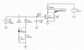
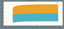
I threw together an example. It may not model exactly like the radio, but it illustrates what happens. The diode rectifies some of the driver signal and adds that DC to the waveform going to the mosfet gate. As the DC increases, more of the incoming waveform is turning on the mosfet (mosfet turns on above 3.5v, give or take .5v).
View attachment 77363
View attachment 77364
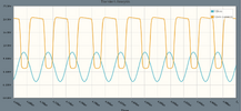
and after it settles, this is what it looks like zoomed in
View attachment 77365
If the diode was backwards, this blue driver waveform would not climb up.
I am not saying the instructions are wrong as I have never done one of those, but when I model this with C149 and C46 as they are in the schematic, I don't get any DC. It needs more drive. I removed the shunt cap (reduced it to 1pF in the sim) and changed the 270p to 680p and thats how I got this waveform.
Again, this is just a rough incomplete circuit model, your scope readings may vary. Mainly did this just to illustrate what that diode is doing.

