• You can now help support WorldwideDX when you shop on Amazon at no additional cost to you! Simply follow this Shop on Amazon link first and a portion of any purchase is sent to WorldwideDX to help with site costs.

BinaryRock

brandon7861

Loose Wire
I Support WorldwideDX.com!
Nov 28, 2018
2,562
2,835
293
Going to roll the dice on having boards made without prototyping it first. I have no idea if this will work but I think I thought it through well. First version is single frequency and set using binary instead of ordering it programmed to a set of frequencies.

Whatever frequency you want, convert the Hz to binary and solder it on the back. I have the parts on the way and I'll be ordering boards tomorrow after I triple check everything. Board is 30mm x 34mm and the output can be direct from the 5351 output, or by turning a resistor 90 degrees, passed through a mosfet at supply voltage (input voltage, not the 3.3v regulator). Should make the output strong enough to work the neighbors. Still contemplating resistor choice there.

This will be my first 4-layer board. I have a few little changes to make but this is about what it will look like. 6-pin header for initial programming only. Power in the 2-pin header.

Edit with updated board views. Ordered today.
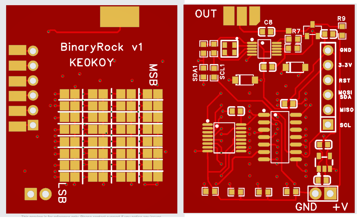
1786653991717.png
 
Last edited:

That is exceptional! Fingers crossed it all works the first production run.

73
Thanks! I sure hope it works because shipping alone hurt so bad ($106) that I ordered 1000 boards instead of 100 so I didn't have to order again. Wasn't much difference in shipping.

The schematic makes sense (to me anyhow) and DRC showed no errors but I'm definitely crossing my fingers anyhow because I am $380 total into those boards now.
 
I guess if these don't work, I'll drill holes in the corner, add a key ring, then drop them off at the local gas stations lol. Nice thing about livin' in the woods, everyone does consignment around here. Ain't like a Kwik Trip with a corporate office. I'll still make it work even if they fail.

Kinda wish I hadn't put my call sign on the silkscreen now.
 
  • Like
Reactions: Cable Guy
These will work great for AM radios but not for a crystal using a varactor for clarifier control or switched pulling for LSB/AM/USB selection.

Maybe the MISO header pin hole can accomodate a wire and double as an ADC for clarifier input. Would need to know the voltage of the wiper centered and at its extremes and program it in for it to work right though. I will try to find a practical solution.

or maybe I could include a clarifier calibration routine that does that for you...
 
These will work great for AM radios but not for a crystal using a varactor for clarifier control or switched pulling for LSB/AM/USB selection.

Maybe the MISO header pin hole can accomodate a wire and double as an ADC for clarifier input. Would need to know the voltage of the wiper centered and at its extremes and program it in for it to work right though. I will try to find a practical solution.

or maybe I could include a clarifier calibration routine that does that for you...
For the Sidebander VI project I connected the clarifier to a +5V source and then used an arduino map function to set the clarifier limits. The hardest part was setting the clarifier pot at it's extremes and recording the voltages for the map. The rest was just math.

Not saying this is what you should do, just providing one possible solution for that particular problem.
 
This is how the Troy Radio synthesizer implements the clarifier. Don't care for the conversion lag, though. The discrete up and down steps you'll hear turning it slowly reveal the speed of the analog-to-digital conversion. I would prefer a second rotary encoder with smaller steps. Probably more of coding headache.

73
 
I was hoping this 10bit adc would hide the steps. If I can get at least 80% of the ADC input range from the clarifier then I should be able to get 1024*.8=819 steps. 5k up and down, 10k total, over 819 steps is 12Hz per step. I was wondering how fast the 5351 library will be and if I need to learn the hardware code (dont want to). I am hoping to use one of the extra binary pads for a clarifier min center max clock input to record the values to eeprom.
 
Well, I just found a problem. I forgot 8 diodes. The only way this will work is if the binary pads are bridged with little diodes (and that sucks, that wasn't the goal). Still functional, but far more difficult for the end user.

With mention of a rotary encoder and all that, maybe I should ditch the decade counter and 8-bit micro and upgrade to a 32-bit micro. That was my problem, I was using a 4017 to cycle through the 8 rows so I could get 32 bits with only 4 inputs. I failed to realize the low is actively driven low too and one output going high could go right into another output that is low via a binary solder connection down the line.

That hurts, but it isn't stopping me. I am going to redesign this, probably with a better micro, and let them solder the parts on too.
 
  • Wow
Reactions: Cable Guy
I was upset at first, but its 3 days of pay lost and my job permits me to spend my free time working on that stuff, so its not that bad. I live pretty much paycheck to paycheck so it slows me down a little but I see potential and I am honestly happy I have the opportunity to add some options. For now I am trying to see if I can fit the diodes and bring the extra micro pins out. Maybe add a couple tri-state buffers that move the 4 data inputs to external pins and run it on the 9th digit of the decade counter so that after it clocks the binary in, it gives all those pins back to the user. I clearly have to put more thought into it, but I see this litte 8 bit micro doing big things lol
 
  • Like
Reactions: Cable Guy
I can see a daughter-board thing protruding from the mass produced prototype board that you have coming, that could hold the diode array maybe, or other circuitry to support your endeavors. Who knows, this could be the beginning of your legacy. Great things can come from failed beginnings. Since you are already in knee deep, you can afford to go a little deeper.
 
  • Like
Reactions: brandon7861
Just learning how to use these microcontrollers in my own circuits without a blue arduino board ziptied to it may have changed my life. Combine that with the ability to design and have boards made (mistakes aside lol), the possibilities are endless and I have been quite exited about it the past week. I am thinking perimeter alarms for camping, long range driveway alarms and all sorts of things now.

Edit: still have not graduated to fpgas or stepper motor drivers yet, so no drones yet :( Some day.
 
  • Love
Reactions: Cable Guy
I can see a daughter-board thing protruding from the mass produced prototype board that you have coming, that could hold the diode array maybe, or other circuitry to support your endeavors. Who knows, this could be the beginning of your legacy. Great things can come from failed beginnings. Since you are already in knee deep, you can afford to go a little deeper.
I got the diodes to fit on the board and I also moved the programming voltage/ground to the power-in header (made it a 3 pin) which freed up two pins on the other header for a total of three ADC pins available for external connection. Now with just a firmware update, this thing should be able to do all sorts of stuff.

Before I order v2, I will wait for the first run to arrive. I want to test one with the diodes on the pad and make sure there are no other problems.
 

dxChat
Help Users
  • No one is chatting at the moment.