• You can now help support WorldwideDX when you shop on Amazon at no additional cost to you! Simply follow this Shop on Amazon link first and a portion of any purchase is sent to WorldwideDX to help with site costs.

.64λ Homebrew

i would not worry about what the analyser says homer, what matters is your radio is happy with the load it sees and the signals are the best you can make them,

heres a plot of a friends homebrew vector, he also felt that the antenna maybe worked better when extended than when adjusted for best analyser numbers, i have not spoken to him about it recently.


http://i5.photobucket.com/albums/y152/ukmudduck/swr.jpg

Hey Bob, do you know how much extending your friend felt would be the better length? Is he able to talk farther than your I-10K?

I still haven't put my S4 back up since two summers ago. From the winds we're having this spring, it looks like we'll have another hot, dry, windy summer. Our grass and trees are already starting to suffer and I might not get any work done again.

Why would Cebik include secrets for tuning the Sigma4 in an article about J-Poles? Was he in the camp that thought the Sigma4 was a modified J-Pole of some sort? Boy, that article is about 70 pages long, and it would burn me out trying to read and comprehend it all. In looking at the sub titles of the 4 sections on J-Poles, I don't see anything that suggest a discussion on Sigma4 tuning. Maybe you can help me out a little with some specific areas of interest that are included for tuning the Sigma 4? If you email me these areas of interest, I will high-lite them and post them up on the forum.

BTW, did you ever get your I-10K to tune the lowest SWR at the resonant frequency of choice, like I did? I think I told you about my success in tuning a couple of years ago when I was testing with my VA1 direct at the feed point. Also did you ever try the 50' foam coax or LMR 400 with 80-85 VF for tuning like Jay suggested in his manual? I found that length also showed me the same match on my VA1, so I could use a feed line to tune and get the antenna up higher, which is more better.

If Jay could make his I-10K hold up good enough to survive your winds, why can't you Brit's copy the construction ideas for you Sigmas or Vectors, and work the long distance you tell us about as your steering the RF.

Then maybe after a little practice at tuning you could tell us how you do it, and we too could all get out better.

Sometimes I talk all the way to friend in Galveston over 75 miles away, on the Gulf coast, with my Starduster at about 46.6' feet high to the hub. Is that good? I do a trick on my Starduster feed line installation that seems to help me get out better. Do you think maybe I'm also steering my RF angle downward like your Vector somehow...maybe by better controlling the CMC like the Gain Master does, while using my bazooka balun design? I know that 1/4 wave radiators are supposed to produce a somewhat higher angled maximum lobe for the RF.

Have you been doing OK? I haven't been doing much radio since last year, so nothing much to report. I also lost your email address somehow, maybe you could PM it to me.
 
  • Like
Reactions: 1 person
i would not worry about what the analyser says homer, what matters is your radio is happy with the load it sees and the signals are the best you can make them,

heres a plot of a friends homebrew vector, he also felt that the antenna maybe worked better when extended than when adjusted for best analyser numbers, i have not spoken to him about it recently.


http://i5.photobucket.com/albums/y152/ukmudduck/swr.jpg

Bob, this will help tremendously. He does have a nice SWR curve on it, and the triple points of resonance looks somewhat familiar. I will be able to look to this as a guideline of sorts when I get back to it.

Thanks!
 
the plot is ccm's homebrew vector eddie, no he did not say at what length he felt it performed best nor do i think one size fits all,
he certainly sees the advantage over his starduster,

yes i can talk further on my vector than on my i-10k or any other 5/8wave, is it just the advantage in height of current maxima, thats at least part of the advantage,

CEBIK did not include anything about the sigma4 lol,
you would have to read the whole article to get a clue as to how the lower 1/4wave of a j-pole radiates, which may be why he told me what he did about the sigma style antennas,
its an interesting article, explains the shortcomings of eznec with certain types of antenna, its not the only article out there that says the same thing,

no i have not tried again to get the i-10k to show resonance and min vswr at the same frequency,
im still pondering on what walt maxwell said in reflections 2 about the lowest vswr always occurring at the self resonant frequency of the load,
i have little interest in simple antennas like 5/8wave ground planes,

my sigma is stronger than the i-10k, a stock sigma with double skinned lower section is as strong as the i-10k probably stronger,
when was the last time you saw a fishing rod built with the step taper schedule of the i-10k?,
its a cheaper way of building a vertical not the strongest way using the same tube sizes,

the new vector is stronger than the old vector but still weak,
i don't think it performs as well if results locally are anything to go by,

i have talked about how i tune up on here and in email with you so has shockwave, its no secret,

75 miles with a starduster @46ft is better than i can do from this location, stardusters are great little antennas even when you don't have ground that seems to equalise antennas, maybe you need to take a road trip to the mojave, get some of that very poor soil for your garden;)
its not a 1/4wave,

w8ji gives ideas on how to isolate such an antenna and why they can often whoop an imax,
anything you do that reduces cm currents from the mast/feedline should help,


nothing interesting to report here either, we don't have stable conditions conducive to antenna testing.
 
There you go, again, Bob.
Now I'm fighting the urge to wrap this antenna up quickly and go back to fiddling with the Vector/Sigma design.

I agree the 5/8λ GP is a simple design, as is this .64 being virtually identical but for length by a few inches. I have contended that I could have a homebrew together, tuned to useful SWR and on the air within two hours if I had the materials laying in front on me on the ground. I maintain that claim even now. What this thread has done is initiate me into the practice of building such an antenna using the MFJ-259B analyzer, and the challenges mount when doing so that I never encountered without this tool.
With only an SWR meter I would have called it good at several points along the way and began to try to collect some contact data in spite of the lousy DX and limited local radio conditions, however, the analyzer has kept me searching for the best combination of matching network(s) and length, top hat or not, etc while preserving a wealthy bandwidth and resonance in the right places.
The experience so far has left me in doubt of the health of some of the antennas I've cobbled together before with respect to the data the analyzer provides. That said, nothing so far has left me in doubt of the TX/RX performance any of them have delivered - the history of both local and DX results are written in the annals of time. The proof of the pudding remains with the taste (I'll put my lobe up against your lobe any time). ;)
My current interest is in whether I have the understanding of the process, and the skill set to get the various pieces of the puzzle together, and if when I do, whether the antenna will measure up to the results I've seen in on the air performance just getting a good SWR on previous constructions.
I hope to learn this tool, learn what makes the electrical variables what they are and how they are affected by mechanical variations, and above all, if the claims I've heard/read that with the SWR/R=/X= etc all in the right places the antenna will be superior to those which do not/may not have those ducks sitting nicely in a row.

Interestingly, Bob's admonition to care less about analytical perfection (where the Sigma/Vector are concerned) and look primarily to results on the air does not come to me as a lone voice. One of my Elmers (yes, I have a couple of those. . . .now where did I put that elmer . . .) constantly chides me for my lately overweening interest in this. Before the purchase of the 259b it was the voice in my head that guided me - no, I am not on medication for the voice . . .
I have no doubt that there is validity to that instruction. Millions of antennas operate satisfactorily currently within those parameters.
But, can I make as good antennas as I have made, or better antennas than I have made, with the use of the analyzer than what I produced without it, as I have been led to expect? There's the burning question.
 
  • Like
Reactions: 1 person
"But, can I make as good antennas as I have made, or better antennas than I have made, with the use of the analyzer than what I produced without it, as I have been led to expect? There's the burning question."

I think you can cool that 'question' off a bit, don't let it burn you. :)
You've pretty well stated the differences between being aware of what a measuring device tells you and what it -means-. How the information relates to what you are measuring and -why-. You can do some really amazing things with almost any 'tool' if you know how to use it. The only 'trick' is in the understanding of what that tool can do and not do, and how to use what it tells you. That can be a real 'trick', and is never that easy to do. It help is you can find someone who's already gone through all that 'learning' and who can show you what they've learned. (No need to make all the same mistakes if you don't have to, right?)
Have fun.
- 'Doc
 
Bob, this will help tremendously. He does have a nice SWR curve on it, and the triple points of resonance looks somewhat familiar. I will be able to look to this as a guideline of sorts when I get back to it.

Thanks!

I think you're right Homer, Bob's analyzer image does clearly demonstrate that reactance forms a nice smooth appearing sinuous type curve, and explains rather well, how and why you were seeing repeating reports of X=0 at other points along your bandwidth. I know when you presented your first 259B reports and this idea popped up, I learned something new that I had never considered about my own work with my analyzer.

I still think you would benefit from recording your data on an actual graph, and then connecting the dots along a more even progression in frequency, and stop using SWR values to determine how your scan will progress to the next step. That would seem to me to give a much clear idea of what is going on with your 259B data and make your comparison work more simple. I think you will also notice that using a well defined step rate, as you scan, will provide much more reliable data compared to your raw numbers...where the frequency is skipping around along some predefined SWR values you select.

I use a step rate of .100 on my graphs, but I think .200 would probably work just as well, and allow for less scans and more frequency range in testing and record keeping.
 
Doc, I'd sure enjoy the benefit of a local expert, but apparently they come few and far between here, and I'm right in the middle.
 
Marconi, I'm taking your advice under advisement. I did do a rather long plot last time, and it was only plotted to the end points of 2.0 SWR. I might have to buy some graph paper seeing I do not like messing with software. The stuff reeks of the smell of frustration.
 
  • Like
Reactions: 1 person
Marconi, I'm taking your advice under advisement. I did do a rather long plot last time, and it was only plotted to the end points of 2.0 SWR. I might have to buy some graph paper seeing I do not like messing with software. The stuff reeks of the smell of frustration.

Yes of course the <2.0:1 end points have to be pre-selected for a <2.0:1 SWR bandwidth curve, but I was talking about the consistency of the data in the rest of the graph, that I think is important for report to report comparisons later on.

I have never plotted the reactance, resistance, or the value of Z, but the data is there to do so. It would be nice if I could duplicate the data Bob's meter shows, and do it all in one second, instead of taking several minutes to an hour or more...to scan, record, and do the plots.

To be honest as to what I can miss using a .200 frequency step rate. I often miss the specific frequency for reactance when it crosses X=0 for a frequency that is not listed on the graph. So, my BW curves look like I never see X=0, and for this reason, I might pass right on by resonance, which goes to show these point are small in the graph. For informations sake: these points are very small adjustments on the antenna too when you get close. If you use adjustments that are 1/4" to a 1/2" you might find yourself going right on past the sweet spot you're looking for.

This said however, I do have the advantage of seeing the capacitive (-) and inductive (+) values on my meter, which is not the case on the 259.

You'll notice in Bob's image that the Vector shows about 1.60BW<2:1 bandwidth, and that is probably not bad considering the reading might have been taken at the feed point. That is a little better BW than my S4 shows when the VA1 is attached to the feed point using an 8" jumper. The jumper, BTW, shows to be transparent on my dummy load vs. when VA1 is connected directly to the DL and that gives me a little room to work below the feed point.

To demonstrate how I find my bandwidth curves on my Antenna Work Sheet's useful, check out my diagnosing a problem I had with the radial stand off used in the bottom of the Sigma4. Check out the attached below.

I had used an Avanti manual to check the dimensions on my S4. My S4 was made by Antenna Specialists, and where the radial stand off went was different than Avanti had originally called for. When I realized the difference in manuals, I thought that was causing the antenna to be high in frequency, so I raised the stand-off up a bit higher on the radials. However, when I scanned it a little around 27.205 I noticed the numbers were about the same as the previous test.

I didn't record the BW data after that fix, but I did recheck the dimensions again, and in the process I noticed that the gamma match was not installed directly in the middle of the two radials where it is supposed to sit directly between them. Well, I fixed that and scanned it again with my Autek. After compiling the data and making the graph I could really see that the antenna went down in frequency a bit...right where I thought it should be at 27.205 mhz and I was fully convinced I had fixed the problem.

If I had not had my reports to compare, I might have missed the distinction for the repairs completely. Did it make any difference in performance? Not that I could tell, in fact when I first installed the old S4, I didn't touch the matching and it was showing and SWR of 1.70 at 27.205. Here again I don't think I saw any difference that I could measure after I re-tuned the antenna.

I figure if I can't see or measure any difference working my radio and going from the top of the bandwidth to the middle and then to the bottom, I doubt better tuning is going to get me excited or show me a bit of difference. I think everybody should be able to do that test...using their radios and seeing how it might effect the performance.

You have to try and understand why all this might have gone unresolved in my understanding just doing the scans and not recording the data and making the graphs.

When I test I record the data, and I work to control each steps I make. I'm not doing my graph at the time, I'm just testing and recording. Later on, and sometimes much later on, I develop the graph and then maybe I can see and understand the trends the data describes. If I didn't do the testing this way and record my stuff, I may have never known for sure what did what. Now when I'm really tuning the antenna, I just have to take the time to develop the data on the graph, so I can see the effect in order to proceed to the next step.

The big deal here is, I can spend maybe an hour or more doing what Bob and his friend can do in seconds. Don't let this idea be of frustration if it doesn't suite your time and purpose, I do it as I have time. Just something else to consider.

View attachment Sigma 4 Work Sheets.pdf

Homer I won't describe here what is what in the attachments, but if you have questions, then just let me know.
 
Last edited:
homer,
heres the only graph i saved of the i-10k first time around with the minivna at the feedpoint, i did experiment again, i made 100+ adjustments while watching the laptop screen and ended up right back where i started,

im not saying there is no room for improvement i just don't have the interest in the i-10k, its about 8ft too short and the radials are in the wrong place;)

http://i5.photobucket.com/albums/y152/ukmudduck/I-10K.png
 
homer,
heres the only graph i saved of the i-10k first time around with the minivna at the feedpoint, i did experiment again, i made 100+ adjustments while watching the laptop screen and ended up right back where i started,
Thanks
im not saying there is no room for improvement i just don't have the interest in the i-10k, its about 8ft too short and the radials are in the wrong place;)

http://i5.photobucket.com/albums/y152/ukmudduck/I-10K.png

:laugh:
 
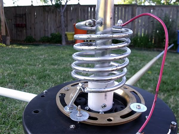
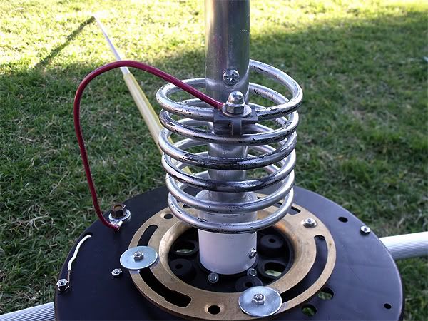
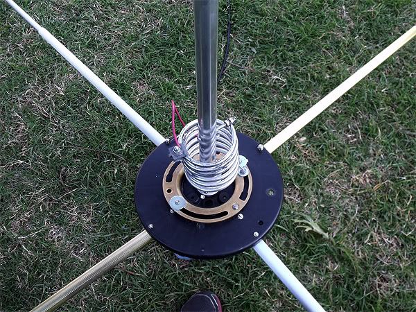
Close up shots of the current matching coil.

F0358.jpg
F0360.jpg


F0361.jpg
 
Is that . . . a toilet flange?
Now; that is what I call 'inventive'/'resourceful'

I was thinking the same thing ROBB.

Waiting for Homer to get his license, he has the "TRUE AMATEUR" can do attitude.

Use what you got and make it work.

Antenna looks good Homer, thanks for the pictures.
 

dxChat
Help Users
  • No one is chatting at the moment.