• You can now help support WorldwideDX when you shop on Amazon at no additional cost to you! Simply follow this Shop on Amazon link first and a portion of any purchase is sent to WorldwideDX to help with site costs.

.64λ Homebrew

HomerBB

Sr. Member
Jan 4, 2009
3,933
2,633
273
68
Rogers, Ar
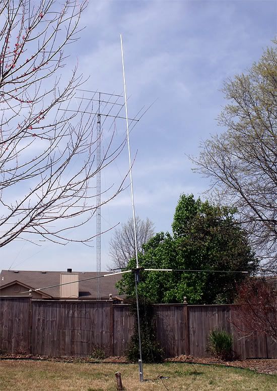
I decided I wanted to put another 5/8λ Omni in the air before I moved on to other antennas, but decided why not go .64 first and see if I like it. To me it looks really short after working with Sigma IV/Vector 4k antennas.

I have to get my photos ready, and post some current results so far with the MFJ-259b. Some of the numbers looks good.
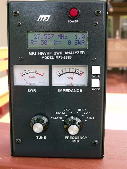
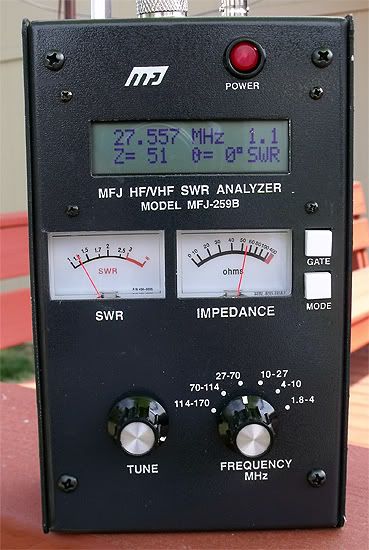
Curiously, I am finding that unlike the complaints of the SWR shifting with power applied to the system, there is no such thing going on so far on this antenna. It is holding the 1.1:1 SWR with the meter in either case.

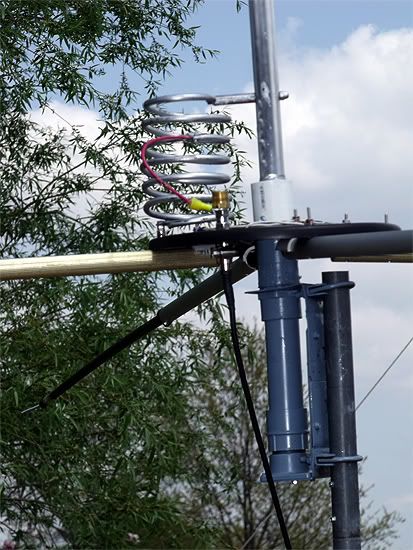
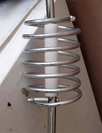
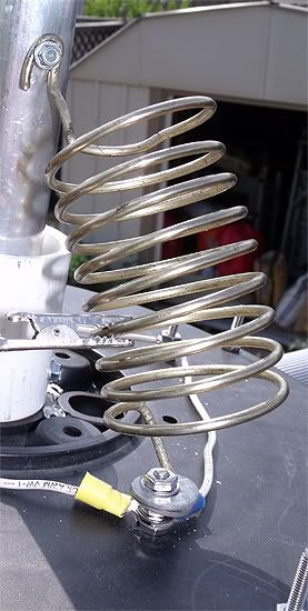
I am working on it at only 8' above ground so things could go South raising it up. We'll see. It's nothing special, 4 radials and a vertical radiator.

I'll be trying to get a working Gamma on it, and revisit the dimensions for the Maco style loop. Right now, the only thing working well is a tapped loop.
More photos tomorrow, hopefully. I'm working too late tonight.

So far not too much to show:
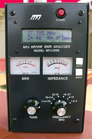
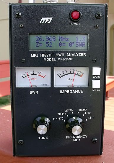
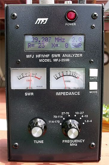
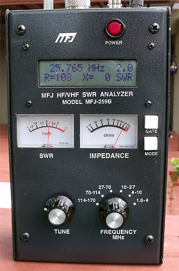
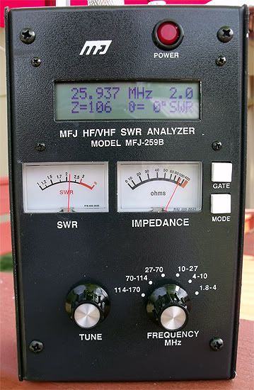
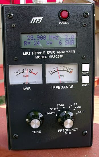
F0044.jpg
F0055.jpg


F0056.jpg
F0059.jpg


2.0:1 SWR limits:

F0049.jpg
F0054.jpg
 

Looking good, Homer! Do I spy the plastic spool end from the old Sirio knock-off for your element support? And when did you score the analyzer??? That's an indispensable tool for the projects you are working on. I have been considering buying one myself.

73,
RT307
 
Thanks, Brett.
It is not the very one, but the other end of the spool.
I got the 259 about a month ago. It's the cat's meow . . .

For those interested in the 2.0:1 SWR bandwidth using the large coil.


F0091.jpg
F0090.jpg


This coil was first manufactured for use on one of my mobile antennas. It was brake line coiled up for use on the antenna.


F0070.jpg


Initially, I'd used this coil which was half the spring from a Dachshund wiener dog letter holder.


F0065.jpg
 
Another good result Homer, but I still don't get how this antenna could be resonant over that wide of bandwidth. On occasion my analyzer might show me X=0 reactance at some frequency, and maybe even over a 0-15 khz range on one of my antennas, but as soon as I move a few khz in frequency...the reactance starts to change, just as I would assume it should.

I'm trying to understand how the 259B works, so how do you do that? If it's a special mode setting...what is the point of the digital value of X to always show a 0 value over the full bandwidth.

I may be wrong about what is shown here, but this is like the antenna is always resonant (X=0) at the selected frequency indicated, and I just don't see how that is possible?
 
Eddie, it is not, what you are seeing is because of the mode that homer is using.
Homer, can you go back and do the same test in the basic mode and post the result?
Thanks.

Eddie, here is a link to the User manual for the 259b that will show you the functions, this will help.
http://www.mfjenterprises.com/pdffiles/MFJ-259B.pdf


Homer, if you are using the advanced mode, the first setting in the advanced mode is:
Z=MAG O=Phase Angle


Impedance is the first mode in the advanced menu. The opening display indicates:
In this mode, the MFJ-259B LCD displays frequency, impedance or Z magnitude (in ohms), and phase angle ( θ )
of impedance. The meters indicate SWR and Impedance. The maximum impedance limit is set at 650 ohms,
indicated by the standard display of (Z<650).

73
Jeff
 
Jeff,
If you look back to the original post you'll see some advance mode photos. In those photos the X= 0 will look like this X= 0° with the degree symbol attached.

In the latest photos I'm using the main mode, which shows X= 0 without the ° degree symbol.
 
I think what Marconi is pointing out, is that it is very wide banded. Perhaps more than it should be. A higher "Q" perhaps?

Doesn't a higher Q mean that there is more capacitance present?
If so; would that explain the wide band of the antenna?
 
What I can do next opportunity is run a series of readings on the main mode and track the X =. It may be that there were fluctuations along the way between the 2.0:1 SWR bandwidth not represented in the thread so far.
 

dxChat
Help Users
  • No one is chatting at the moment.