• You can now help support WorldwideDX when you shop on Amazon at no additional cost to you! Simply follow this Shop on Amazon link first and a portion of any purchase is sent to WorldwideDX to help with site costs.

.64λ Homebrew

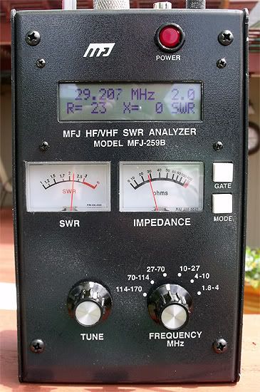
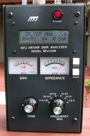
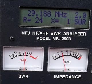
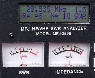
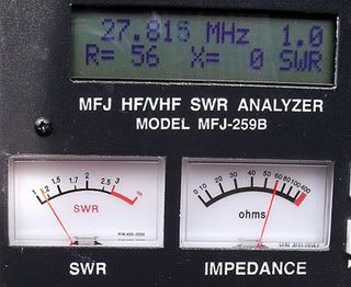
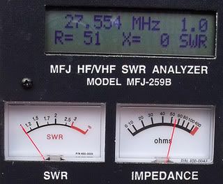
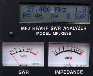
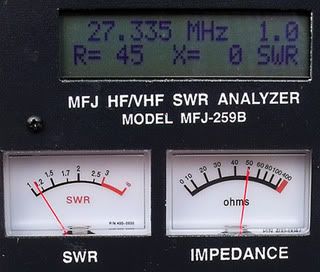
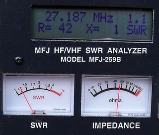
Wow, OK......Like Eddie, i find it very interesting that you have X=0 over that range....yes please do show some more points in the middle.
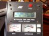
My good Camera quit working, and all I have is my cell phone at the moment, but I will run some numbers on my I 10K and post them if it is readable.

73
Jeff
 
The wider banded an antenna is the LOWER it's 'Q'! Meaning that the lower the 'Q' the less efficient the thing is. That 'wider than a barn door' usable band width means it's equally 'bad' over a wider frequency range than an antenna with a higher 'Q'.
Sound sort of counterproductive? Yep, and it is, depending on what you expect. The same thing for having a 'X = 0' with a 'R = 50' over a wide range. That just can't happen without lots of compensating not possible without some sort of 'adjusting' going on. A fixed length with a variable frequency always means a variation in 'R and X'. So where is that 'extra' 'R and X' coming from??
- 'Doc
 
  • Like
Reactions: 1 person
Thanks, Brett.
It is not the very one, but the other end of the spool.
I got the 259 about a month ago. It's the cat's meow . . .

For those interested in the 2.0:1 SWR bandwidth using the large coil.


F0091.jpg
F0090.jpg


This coil was first manufactured for use on one of my mobile antennas. It was brake line coiled up for use on the antenna.


F0070.jpg


Initially, I'd used this coil which was half the spring from a Dachshund wiener dog letter holder.


F0065.jpg

I was trying to figure out what shows what with the images on your 259B. I guess I should have been more clear.

I was wondering what mode shows the X=0 in the results above, not withstanding the degree symbol you comment about. I may have missed that degree symbol distinction earlier too, so I've learned something new.

However, regarding your response. I think I recall you telling us that you were using resonance mode when I asked the question before, and in that case you were scanning across the 40 channels for CB. In the images above I see this antenna showing the same X=0 across the entire bandwidth of the antenna.

BTW, IMO it is also amazing that your antenna is showing almost 3.5 mhz in bandwidth, and no one as mentioned that. I have several 5/8 styled monopoles, and none show anywhere near that bandwidth. Another plus for your design and model.

Homer, I mentioned earlier that my posts have raised concerns by others before, but don't let my words upset you. My purpose is purely out of curiosity with something I see and don't understand.
 
OK, The quality of these pictures are crap, but it is the best I can do at the moment.
Jay says the I10K has a usable bandwidth of 1.3 to 1.4 Mhz with SWR of 2 to 1.
I should play with the match and length of the antenna and probably get this a bit better, but I threw it up one afternoon, checked it with a SWR meter to make sure It was good on the phone band on ten and and have not touched it since.
The Last 2 photos I wanted to see were my MFJ would do the X=0 on both ends, and there you go.
I have never wanted to do this, that is why I found it Odd to see it on Homers, but there it is.
I guess i need to play with the analyzer more ...... I always look for 50/0 or as close as i can get with out too much work.
Interesting.
The band width of your home brew antenna is huge.


73
Jeff
 

Attachments

  • 20120330143947.jpg
    20120330143947.jpg
    107.1 KB · Views: 4
  • 20120330144042.jpg
    20120330144042.jpg
    113.1 KB · Views: 4
  • 20120330144134.jpg
    20120330144134.jpg
    123.3 KB · Views: 4
  • 20120330144240.jpg
    20120330144240.jpg
    128.6 KB · Views: 3
  • 20120330144330.jpg
    20120330144330.jpg
    118.9 KB · Views: 2
  • 20120330144448.jpg
    20120330144448.jpg
    118.6 KB · Views: 3
  • 20120330144518.jpg
    20120330144518.jpg
    129.1 KB · Views: 5
I was taking pictures and posting, just read Marconi`s post.
I to hope you don`t think I was saying you were wrong in any way as well, just found it very interesting your results and ASSumed you were using the advanced mode.

73
Jeff
 
An interesting quote from Wikipedia:

Bandwidth

Although a resonant antenna has a purely resistive feed-point impedance at a particular frequency, many (if not most) applications require using an antenna over a range of frequencies. An antenna's bandwidth specifies the range of frequencies over which its performance does not suffer due to a poor impedance match. Also in the case of a Yagi-Uda array, the use of the antenna very far away from its design frequency reduces the antenna's directivity, thus reducing the usable bandwidth regardless of impedance matching.

Except for the latter concern, the resonant frequency of a resonant antenna can always be altered by adjusting a suitable matching network. To do this efficiently one would require remotely adjusting a matching network at the site of the antenna, since simply adjusting a matching network at the transmitter (or receiver) would leave the transmission line with a poor standing wave ratio.

Instead, it is often desired to have an antenna whose impedance does not vary so greatly over a certain bandwidth. It turns out that the amount of reactance seen at the terminals of a resonant antenna when the frequency is shifted, say, by 5%, depends very much on the diameter of the conductor used. A long thin wire used as a half-wave dipole (or quarter wave monopole) will have a reactance significantly greater than the resistive impedance it has at resonance, leading to a poor match and generally unacceptable performance. Making the element using a tube of a diameter perhaps 1/50 of its length, however, results in a reactance at this altered frequency which is not so great, and a much less serious mismatch which will only modestly damage the antenna's net performance. Thus rather thick tubes are typically used for the solid elements of such antennas, including Yagi-Uda arrays.

. . .

The bandwidth characteristics of a resonant antenna element can be characterized according to its Q, just as one uses to characterize the sharpness of an L-C resonant circuit. However it is often assumed that there is an advantage in an antenna having a high Q. After all, Q is short for "quality factor" and a low Q typically signifies excessive loss (due to unwanted resistance) in a resonant L-C circuit. However this understanding does not apply to resonant antennas where the resistance involved is the radiation resistance, a desired quantity which removes energy from the resonant element in order to radiate it (the purpose of an antenna, after all!). The Q is a measure of the ratio of reactance to resistance, so with a fixed radiation resistance (an element's radiation resistance is almost independent of its diameter) a greater reactance off-resonance corresponds to the poorer bandwidth of a very thin conductor. The Q of such a narrowband antenna can be as high as 15. On the other hand a thick element presents less reactance at an off-resonant frequency, and consequently a Q as low as 5. These two antennas will perform equivalently at the resonant frequency, but the second antenna will perform over a bandwidth 3 times as wide as the "hi-Q" antenna consisting of a thin conductor.


http://en.wikipedia.org/wiki/Antenna_(radio)
 
  • Like
Reactions: 1 person
w8ji has some interesting comments about Q and loss in a gamma fed design

A thicker gamma conductor also lowers operating (loaded) Q. This is a series-resonant system, operating Q is set by the amount of reactance in series with the load resistance (50 ohms). Reducing operating Q has the effect of increasing bandwidth while simultaneously reducing loss and increasing power rating.​
Note that bandwidth increased while efficiency increased. This happens in many cases. Popular folklore tells us narrow antennas are efficient, but that is true only in a few specific cases. In most cases, bandwidth by itself tells us nothing about system efficiency!​


Omega and Gama Matching
 
I don't take anything said as offense. I post so folks can get involved, and the questions asked and answered clear the air on the threads.

I see your results, and I will do mine again as I said with stops at points of interest - 2.0, 1.5, t5, .405, .185, .965 and the mid point of resonance.

Anything else?

If dimensions matter, the antenna is 23' long with 4 sizes of 6' tubing from 1/2" > 3/4" > 7/8" > 1-1/8" diameter from the top to the bottom. The lowest 10" of the bottom is down into the mounting bracket/insulator section. The radials are 4 x 9' with 2.5' x 3/4" tube > 6' x 1/2" tube > 1' x 1/4" rod construction.

The coil is a 6" H x 3.25" D x 6.5 wraps of 5/16" tubing.

Perhaps only 8' from the ground has induced some ground losses that affect the low readings. To test the efficacy of the radials I measured with the step ladder under the radials next to the antenna and with it removed from beneath the antenna to see if there was any fluctuations in the readings. I detected none. Neither scientific, nor conclusive for a test, but the thought is nevertheless in my head about ground effects. I will have to get it higher up I guess and see what happens there.
 
w8ji has some interesting comments about Q and loss in a gamma fed design

A thicker gamma conductor also lowers operating (loaded) Q. This is a series-resonant system, operating Q is set by the amount of reactance in series with the load resistance (50 ohms). Reducing operating Q has the effect of increasing bandwidth while simultaneously reducing loss and increasing power rating.​
Note that bandwidth increased while efficiency increased. This happens in many cases. Popular folklore tells us narrow antennas are efficient, but that is true only in a few specific cases. In most cases, bandwidth by itself tells us nothing about system efficiency!​


Omega and Gama Matching
Bob,

Are you speaking only of w8ji's comment regarding gamma fed antennas, or is some of this comment your observation on my antenna?

re
bob85 said:
Note that bandwidth increased while efficiency increased.

If not, may I ask what your thoughts may be?
 
homer,
it was in reference to w8ji's comments and the wiki article you posted and many more articles about the claim that high Q antennas have less loss or that an antenna with a wider bandwidth by its own nature is lower Q and more lossy than a narrow banded high Q antenna when the opposite is true,
no referance to your antennas(y)
 
Well, I certainly invite your comments as much as anyone's.
I have the capacity to try to understand a variety of points of view, and especially when someone clearly has a great understanding of the material.
 
I retested and photographed the series of analyzer readings this morning. Before hand I discovered a poorly soldered coax end and repaired it.
So here they are in the increments of interest, I hope, starting with the highest 2.0:1 frequency.


F0093.jpg
F0094.jpg


F0095.jpg
F0096.jpg


F0097.jpg
F0098.jpg


F0099.jpg
F0101.jpg


F0102.jpg
F0103.jpg


Each reading represents where I first and last encountered these particular readings as I went down the bands - 2.0, 1.5, 1.0 - and T5, .405, .185, and .965. Maybe there is more info regarding X= shifts along the SWR curve.

All readings were done in the main mode only.
 
Jeff,
If you look back to the original post you'll see some advance mode photos. In those photos the X= 0 will look like this X= 0° with the degree symbol attached.

In the latest photos I'm using the main mode, which shows X= 0 without the ° degree symbol.

In those early-in-the-thread pictures, that looks like the Greek letter Theta
θ rather than a letter X. Theta represents the phase angle between resistance and reactance, and is therefore expressed in degrees.
 

dxChat
Help Users
  • No one is chatting at the moment.