• You can now help support WorldwideDX when you shop on Amazon at no additional cost to you! Simply follow this Shop on Amazon link first and a portion of any purchase is sent to WorldwideDX to help with site costs.

.64λ Homebrew

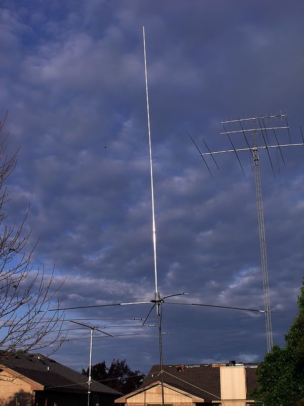
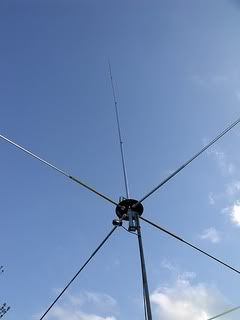
OK, The quality of these pictures are crap, but it is the best I can do at the moment.
Jay says the I10K has a usable bandwidth of 1.3 to 1.4 Mhz with SWR of 2 to 1.
I should play with the match and length of the antenna and probably get this a bit better, but I threw it up one afternoon, checked it with a SWR meter to make sure It was good on the phone band on ten and and have not touched it since.
The Last 2 photos I wanted to see were my MFJ would do the X=0 on both ends, and there you go.
I have never wanted to do this, that is why I found it Odd to see it on Homers, but there it is.
I guess i need to play with the analyzer more ...... I always look for 50/0 or as close as i can get with out too much work.
Interesting.
The band width of your home brew antenna is huge.

73
Jeff

Jeff, the following is not-withstanding the issue with Homer using the mode showing the phase angles instead of reactance.

I plotted Homer's last image results on one of my Antenna Work Sheets below. I did not add the frequencies that Homer used, so don't let that confuse the report.

View attachment Homer's bandwidth curve.pdf

However, even after you posted your images, I'm was still not sure what was happening that would causes both of your 259B's to coincidently suggest to me there was resonance at both ends, and somewhere else near the middle of the antennas bandwidth, excepting maybe that it was just coincidence. Now, that both of your reports are showing some reactance going up and down over frequency, as we might expect, this is not so confusing to me. I didn't see that in the beginning, and thus I asked a question of a young man that I admire and he gave me only a curt answer.

Jeff, what did you really think regarding your unexpected results?

I went back and checked, and I discovered that I've seen such results before with some of my bandwidth curves, but to be clear, that was not what I was asking Homer about in the beginning.

For sure, my meter does not appear to be as happy, if that is what is happening here, when using the frequency control knob or else something else is going on. That being a result that shows such a liberal X=0 reactance over the range as I saw indicated in Homer's first images, 1st over the CB bandwidth, and then later over the whole bandwidth for his antenna.

In my case, I have trouble sometimes just getting X=0, and for sure when I'm very close to X=0. Is that normal or not, I'm not sure, but I do know that reactance should change in fairly small increments with such measuring devices.

On the other hand my bandwidth chart does not look for specific values for X or R, it focuses on a balanced frequency excursion. Now my antenna tuning chart does allow me to search out the desired values for X, R, SWR, Z, in my process toward tuning.

IMO, zero reactance should generally indicate only at somewhat precise points, and the curve may show up as a sinuous shaped curve at times. If such results repeat it is generally over a very small range that should be very narrow, maybe even so narrow as to miss X=0, completely as you attempt to scan in frequency.

I think Homer's main mode images are still showing a rather broad range with X=0, and if that is possible, then that should be very good. I see X=0, from 27.855 - 27.335, which is .52 mhz and that is wider than the whole CB bandwidth at .44 mhz. If true, you can't beat that for resonance, and coming from a homemade antenna, I would consider that remarkable.

I have seen such results on my meter as noted in the I-10K graph below, where I also see several values for X=0, or small values of reactance being repeated within the whole bandwidth. My graphs might tend to show that happening when the reactance is going from inductive to capacitive, and the 259B does not display such a value for the reactance on its display, but MFJ does give the user a routine for establishing such a true value...based on a much closer reading of frequency results.

Technically I can't describe why this happens in the case of reactance, or if it makes any difference to the antenna results, but I doubt it makes any results that I could be detected just operating my radio.

If I'm right here, then I see nothing wrong with Homer's results, but IMO if reactance is to be ignored, then a fuller understanding is also likely being ignore. One might as well just consider using an SWR meter instead.

Hopefully this report will demonstrate much of my opinions as noted above.

View attachment I-10K bandwidth.pdf
 
Last edited:
Thanks, Marconi.
Later this evening I will be able to read over your post/results again more closely.
If I was the one who was curt, I apologize. One question you asked was what I had done with the antenna, and I had only the answer I supplied, just put it together and run the meter on it. I had not intentionally done anything special.
I'll give you a call soon as I can if it's okay.
 
Jeff, what did you really think regarding your unexpected results?
My first assumption was that homer had X=0 over the entire range and I jumped to the conclusion that it was the different mode, I was wrong.
As for my own results i usually do not focus on looking for X=0 over a range like that...I was always looking for low SWR + r=50 and x=0 ( something I never got with the I 10K by the way, it was always off just a little bit, or maybe I am lazy and did not put enough effort into reaching that goal) because my goal normally is to just tune something.
I have never taken the time to record and plot things like you and some of the guys here do, you have a much more inquisitive/analytical mind than I.
So even after owning the mfj for a long time I had not ran an antenna over a wide range and recorded the numbers.
I guess if i had taken the time to record stuff, it would not have seemed so odd to me.
Homers wide bandwidth kind of threw me off, and like Doc, we have always been taught that a wide banded antenna is not as efficient as a narrow banded one.
It would not be the first time I would have to change my mind about how antennas work, RF is a little perplexing at times.

73
Jeff
 
Thanks, Marconi.
Later this evening I will be able to read over your post/results again more closely.
If I was the one who was curt, I apologize. One question you asked was what I had done with the antenna, and I had only the answer I supplied, just put it together and run the meter on it. I had not intentionally done anything special.
I'll give you a call soon as I can if it's okay.

Just to be accurate Homer, what you claim now that I asked above earlier is not correct. See below exactly what I asked, the question had nothing to do with the antenna per se.

Marconi said:
Another good result Homer, but I still don't get how this antenna could be resonant over that wide of bandwidth. On occasion my analyzer might show me X=0 reluctance at some frequency, and maybe even over a 0-15 kHz range on one of my antennas, but as soon as I move a few kHz in frequency...the reluctance starts to change, just as I would assume it should.

I'm trying to understand how the 259B works, so how do you do that? If it's a special mode setting...what is the point of the digital value of X to always show a 0 value over the full bandwidth.
I may be wrong about what is shown here, but this is like the antenna is always resonant (X=0) at the selected frequency indicated, and I just don't see how that is possible?

Nobody likes to have words put in their mouth as some sort of petty excuse for not having answered a simple question.
 
My first assumption was that homer had X=0 over the entire range and I jumped to the conclusion that it was the different mode, I was wrong.
As for my own results i usually do not focus on looking for X=0 over a range like that...I was always looking for low SWR + r=50 and x=0 ( something I never got with the I 10K by the way, it was always off just a little bit, or maybe I am lazy and did not put enough effort into reaching that goal) because my goal normally is to just tune something.
I have never taken the time to record and plot things like you and some of the guys here do, you have a much more inquisitive/analytical mind than I.
So even after owning the mfj for a long time I had not ran an antenna over a wide range and recorded the numbers.
I guess if i had taken the time to record stuff, it would not have seemed so odd to me.
Homers wide bandwidth kind of threw me off, and like Doc, we have always been taught that a wide banded antenna is not as efficient as a narrow banded one.
It would not be the first time I would have to change my mind about how antennas work, RF is a little perplexing at times.

73
Jeff

Jeff, I agree what happened in your case, not plotting bandwidth is not a big deal, but I do it in order to get a better idea for what happens when I tune my antennas.

Homers wide bandwidth was a surprise to me too. I've already said I have never see such with any 5/8 type antenna I have. Most of those are less to way less than 2 mhz in my experience. I questioned Homer because I didn't understand what it was I was seeing, while considering the fact his antenna was showing just such a 3+ mhz bandwidth, and showed the value of X=0 over most of the bandwidth. And, my crystal ball is broken.

I have also heard the old claims about more bandwidth = less effectiveness and efficiency, until I experienced working my Gain Master. I still can't answer that issue unless it all has to do with its balanced feed point.

I agree completely with your last comment, even though I realize that is not a common consideration with most CB'rs regarding antennas.

Since I've likely spoiled my further participation in this thread, I'm out of here.
 
  • Like
Reactions: 1 person
Just to be accurate Homer, what you claim now that I asked above earlier is not correct. See below exactly what I asked, the question had nothing to do with the antenna per se.


Nobody likes to have words put in their mouth as some sort of petty excuse for not having answered a simple question.

Okay, Marconi, I feel chastised. Just hit me with a stick. I completely misread the whole thing, and did not do it intentionally. Not looking for any petty excuses, I just got it all wrong.
Hopefully you can see the question marks after my reply. I just wasn't sure of what was at issue. Until Jeff steered me in the right direction I was not sure - just confused a little. The 259B is new to me, but I did think as the thread went along some of the answer was cleared up.

Homer said:
Marconi, How am I doing it?
Putting the antenna together and running the 259B on it . . .
confused1.gif
By all means stay in here and enjoy the thread. I value your input and can take it if you think I screwed up.
 
I moved the antenna up just 5 more feet to 13' from the ground. The SWR curve slid down the band, and a preliminary look at the numbers seem to indicate a narrowing of the bandwidth, but I'm not sure yet. I did not have time to check it carefully.

Perhaps my theorizing ground losses affecting the readings on the low mounted antenna have merit. . . I will retune for match then check it out some more.
 
Hey Homer,

It was great to hear you again, this time on .400 a couple weeks back.

Just thought I'd mention, if you're right at 23' from where the coil connects to the radiator then you should tune X=0 & 1:1 around Ch15. I went through the measurements while I was helping a friend with his homebuilt coil fed .64 and he needed to shorten it to 22' 9.5" for perfect tuning on .400.

Your mileage may vary :blush:

I'll be real interested in hearing about how well it performs, especially compared to your homebuilt Vector, from which you have had such great performance.
 
Thanks for the heads up on the length, NB. I may have to do some length adjustment to get where I need to be at great5er height.

The performance reports will have to wait until I'm actually at working heights comparable to those I used the V4k.
 
No problem Homer, I accept that you misread my post. I get excited sometimes, so you'll have to forgive me. I took a nap and everything seemed OK after I woke up, but I felt bad having crossed horns with a buddy.

Like I told Jeff, I looked back at some of my old bandwidth charts, and I saw where on occasion I had similar results across the BW of certain antennas...where the reactance unexpectedly seemed to repeat again at some other point across the BW. I have one I-10K chart that I think even showed three such events in resonance.

In these cases the antenna's reactance was shifting from being inductive to capacitive (+ to -) or visa versa. That may happen on the longer antennas that are not physically resonant, but I'm not for sure what causes it otherwise.

I hope I can continue to tap your brain and your thinking as you progress in learning to use your new 259B. Since you have several options under a mode and gate switch, it would help me understand better if maybe you could just mentioned what function you're in with your images, OK?
 
Last edited:
No problem, Marconi.

I'll make sure all the info is added to each post.

As I stated, the bandwidth seems to have shifted downward some with the raise to 13'. And perhaps the bandwidth shrunk some, and the fluctuations in the X=0 is not so eratic.

What I have to do first is rediscover my point of resonance and tune to 27.400 then see what is what. I had only a few minutes today to look at it and I am

27.385
SWR -- 1.4
R = 46
x = 6

I think. That is in the main 259 mode.

When I get the thing right again I can recheck the bandwidth and match across the band.
 
Last edited:
I have tried for a significant part of the day to get this antenna where it ought to be.
No going there with the current matching system. A .64λ antenna length antenna should by nature be resonant lower than where I operate, so I am not surprised that the only good read from the 259B was on 26.125.

SWR = 1.0
R = 50
X = 0

On 27.400 the best I got today after trying two different coils was with one of smaller coil diameter, and more wraps:

SWR = 1.2
R = 48
x = 8

This was with a vertical length of 22' 10" as opposed to 23'.

Some physical changes were done to improve integrity and appearance of the antenna.

F0109.jpg
F0110.jpg


F0112.jpg
F0113.jpg


When you look at my photos there is no disputing that this is a homebrew. The brass floor flange is there to add strength to the spool end disc on which the GP radials are mounted, and to serve as the conductor between all the radials.
 
Homer, did you happen to take some time to radio check and compare the antenna to your AstroPlane in the background, before and after you made the changes?

Have you tried changing the feed line length while using the 259B to see if that made any difference in your results?
 
Homer, did you happen to take some time to radio check and compare the antenna to your AstroPlane in the background, before and after you made the changes?
No. there's no feed line hooked on the AP. It is just being stored there.
Have you tried changing the feed line length while using the 259B to see if that made any difference in your results?
Yes. A single electrical 1/2λ coax showed absolutely no difference in readings on the analyzer than 1/2λ electrical x 6 length.
I also tried the analyzer directly into the antenna with no feedline, but that did not work. I think it was too close to the radiating antenna.
 

dxChat
Help Users
  • No one is chatting at the moment.