• You can now help support WorldwideDX when you shop on Amazon at no additional cost to you! Simply follow this Shop on Amazon link first and a portion of any purchase is sent to WorldwideDX to help with site costs.

6m Larcan Conversion

The problem I have with lifting the bias line during receive is that the module would need to be modified and it wouldn't slide in and out of the drawer properly.

Also modifying the module will mean it can not be swapped to use the drawer with different band amplifiers. I'd like to build with the possibility of swapping modules for 50MHz, 144MHz, 222MHz, or even a few cable changes to parallel modules.

Neither of these is much of a concern if you are using a single module for use on one band only.

I have four 4-terminal RF switches each with an added SPDT switch for status. Two will be used per amplifier. I'll use one switch to control the other. The second switch will turn bias on and off. That way if one switch fails the module remains off. It will also prevent hot switching during the on command. I need to find a way to do the same when shutting off.
 
Last edited:
You could always mod all modules by simply breaking the bias line and extending a pair of wires out to a separate connector whose mating end is connected to the control relay. That way the same control relay can be used with any and all modules and the modification is quite minimal to simply break a wire and install a small two pin connector.
 
I had a look at the rear panel DC connector. Two pins are soldered together with a copper strap between them. Remove the copper strap. The large stud is the PA connector. The small pin powers the bias board. Switch the 50VDC on the bias pin and problem solved. No mods to the PA and easy to swap modules.
 
Hmmm........I'll have to take a closer look at that.

BTW Warren, do you remember what channel those IPA modules I got the other day were tuned for? Just curious as to how far they may be from 2m. I know they were designed for something like 160-230 MHz as marked on the I/O splitter/combiners. Hopefully they will pass 144 MHz without an issue. I suspect they should.


Never mind. Had a small brain fart. Channel 8, 180-186 MHz right?
 
Last edited:
All the high band 1kW amplifiers were built for 174-230MHz, so I'm assuming the driver was the same. Wide band with no tuning involved. Swap the modules between transmitters regardless of channel.

The driver does not use the VSWR / bias board that is present on back of the 1kW modules. I'll try to dig up the schematic diagram to see how it can be used.

I have gain response curves for the 1kW PA modules. They drop quickly below 174MHz. No idea what response to expect from the driver.
 
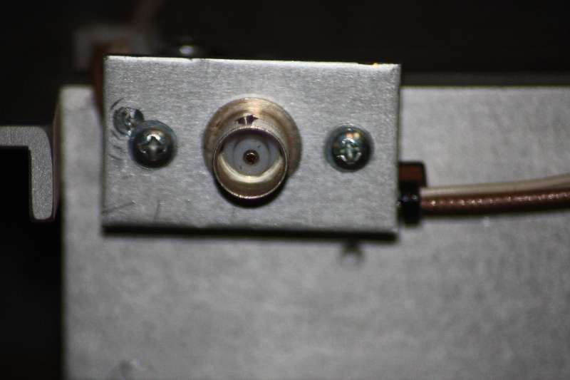
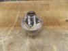
Well I finally got around to getting a bit of work done on the Larcan module. I needed to change the proprietary input/output connectors on the module to something a bit more useful. The input connector looked somewhat like a flared BNC connector as can be seen on the left below.


img2341rc.jpg


It was replaced with a simple BNC connector. RF power at this point is only in the order of 10-12 watts so power handling was not a factor and a BNC will do nicely.

image001etz.jpg


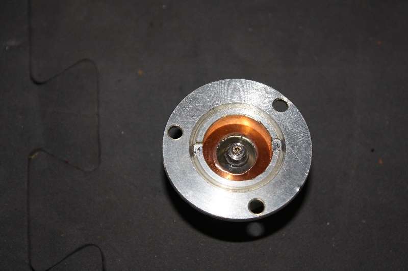
The output connector posed a bit more of a challenge especially if one did not want to simply hack off the old connector and mount a new connector on an L bracket and call it done.


img2343c.jpg


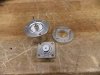
I decided to see if I could adapt the existing connector to accept either a type N connector or better yet an SO-239. I say "better yet" as the SO-239 is still quite acceptable for use at 50 MHz and the center pin is more robust and will handle more connect/disconnect cycles than an N connector as well as handle more RF power. This point will have as much as 1200 watts so having a good connection is mandatory. I started by removing the original connector and taking it apart. I noticed that an SO-239 chassis connector will almost fit inside the original connector and if a washer of the proper size was found it could be made to fit by inserting it from the rear of the connector and it could be held in place by abutting against a flange in the connector towards the front and by using the large silver plated threaded ring screwed in from the rear to hold everything in place.Below are the parts I had to work with showing the connector body and large clamp ring on the left as well as two pieces of PC board material used with the original connector on the bottom. The pieces on the right of the picture are what I had to make or salvage.

image007lr.jpg


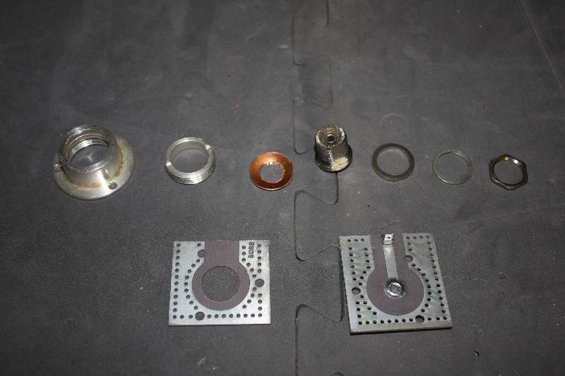
I needed a washer that the SO-239 chassis connector would fit inside of while the outside would in turn fit inside the original connector. The closest I could come up with was a 12mm washer that I had tons of at work although a 1/2 inch would work just as well. The 12mm I had was slightly thinner however and easier to work with. I used stainless steel BTW as it is not good practice to use ferris materials to carry high RF currents. I first worked on the outer diameter by installing the washer on a tapered head bolt so that the washer would be centered perfectly. The bolt was then placed in the chuck of a cordless drill. This allowed the washer to spin without a wobble. Next I placed the washer against the wheel of a power sanding disk and while squeezing the drill trigger I slowly ground the washer down to a smaller diameter by having the sanding disk rotate in one direction while the drill spun in the opposite direction. Precision was the name of the day as the flange is very small and taking too much off would make it useless.After getting to fit perfectly I drilled a 5/8 hole in the center to accept the chassis connector. You should work on the outer dimension first as when you drill the center hole any offset from perfect will cause the washer to wobble and make it very hard to achieve a perfectly round adapter.The finished product can be seen immediately to the right of the chassis connector. The other washer and hex nut came with the chassis connector. Here is the result below.

image008au.jpg


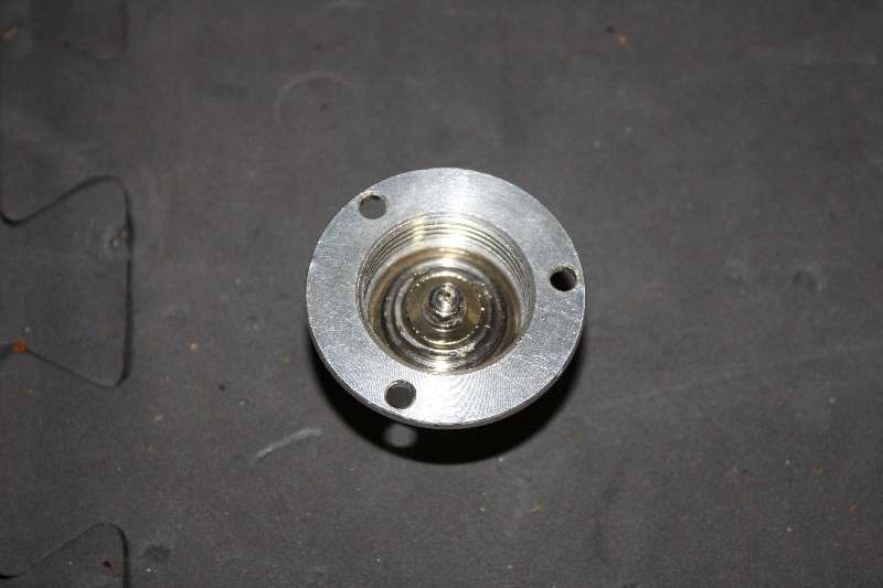
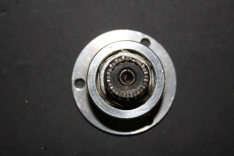
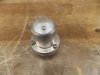
I also need a small bushing to take up the tiny bit of slack as the silver threaded ring would bottom out in the original connector before the adapter was tight. A simple washer made from copper was made as it had to bend somewhat due to the projection of the center rearward into the original connector. It can be seen in the picture above . Here it is in place in the new connector being held in place with the threaded nut. It is important that the nut be seated all the way and is flush with the rear of the original connector and not protrude as this will interfere with mounting later.


image010dg.jpg


This is where it pays to be precise in your measuring and drilling. There is zero clearance for the hex nut. in fact I used the sanding disk to ever so slightly take the points off the nut so it would fit.

image004yz.jpg


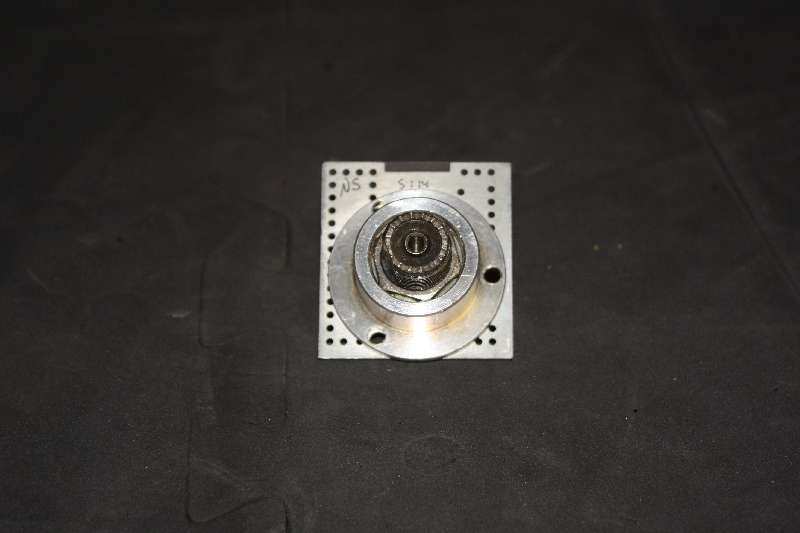
The finished connector mounted on the PC board for final mounting.

image011tf.jpg


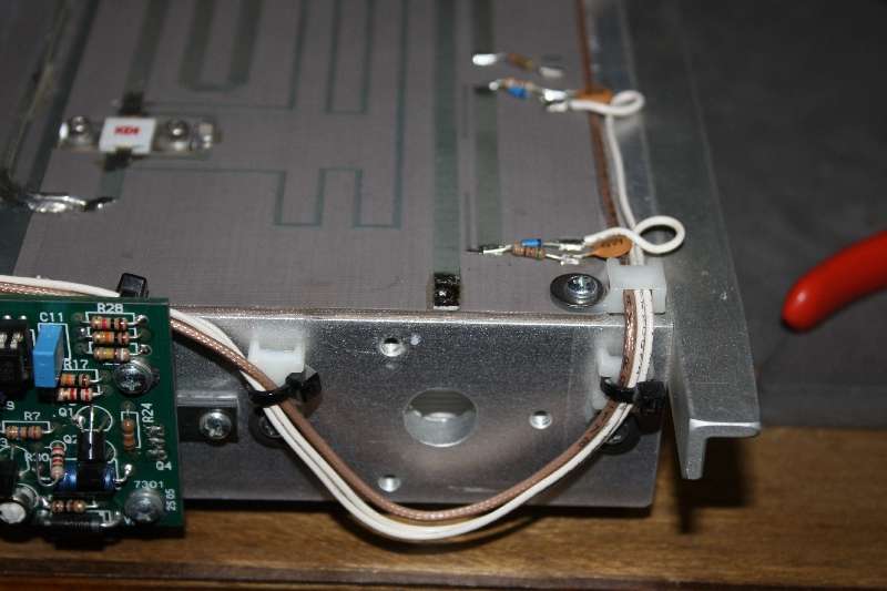
Mounting location of output connector.

image013qp.jpg


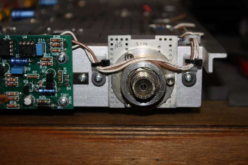
New connector mounted in place.
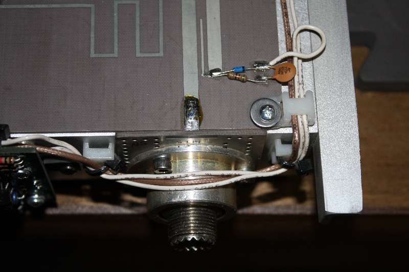
image014sh.jpg


And soldered.

image015sw.jpg


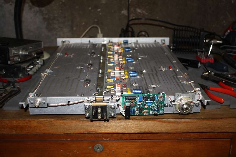
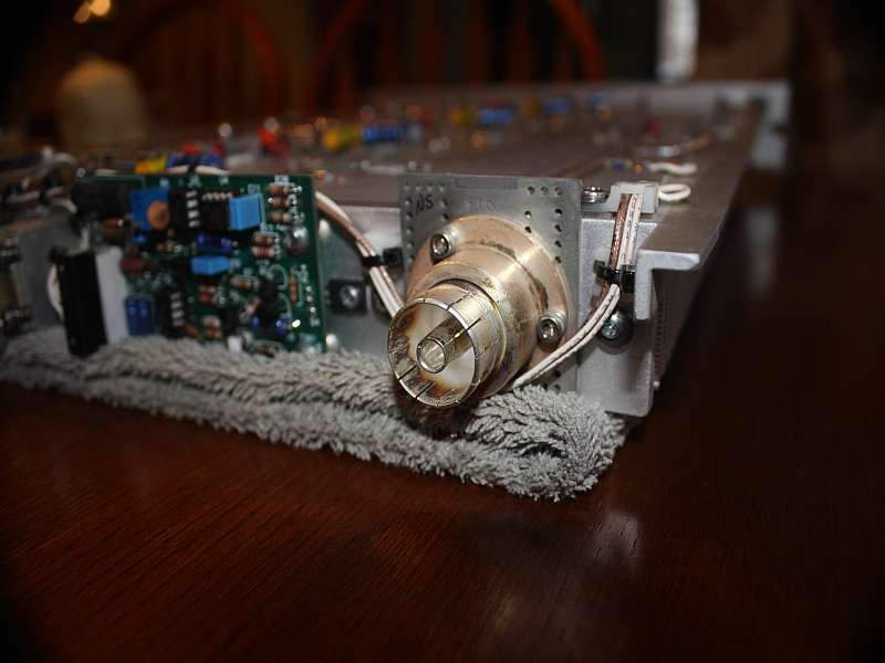
Overall picture after installation complete.


image016p.jpg


BTW I did NOT check the new connector for shorts with an ohmmeter before installation. :unsure: I used a megger from work instead. (y) It only uses 500 volts but that is good enough for me. No shorts or excessive leakage was noted.

I decided to try this method of making a new connector as I did not like some others I have seen. they were basically just a chassis connector mounted on an L bracket or a small piece of metal and mounted on stand-offs or spacers. I like the looks of my connector as it somewhat preserves the original looks and at the same time provides a more finished look. Next comes an RF shield for the component side and some sort of cabinet for it.
 
Did a little more work the past day or two. Got the 50 volt 60 amp power supply wired up with 4 ga. wire and a set of heavy duty Anderson power pole connectors I salvaged from an old IBM System 36 main frame computer many years ago. I installed some toroids on the DC power leads as well as looped the AC power cable (10 gauge 3 wire for 240 VAC input) through a couple large toroids to be on the safe side in an attempt to minimize any RFI from or to the power supply. I also took a chance and ordered a pair of matching meters directly from China via Ebay. They seem to have done a LOT of business and I paid through Paypal so it should be fine. First time I ever dealt directly with a Chinese company so fingers are crossed. The meters are matching and about 2 1/2 inches square. Larger would be better but these will do. One is a 50 volt DC meter and the other is a 50 amp DC meter and it includes the necessary 75mv@50Amps meter shunt to make it work properly. Free shipping and the total for the meters was less than $14.00 so it was well worth the risk. Now I just need to come up with a decent enclosure for it and I am good to go. It is hard to find something deep enough (24 inches) to fit and yet not too huge to fit on the desk. I have a nice tabletop rack cabinet but it is only about 14 inches deep as is the floor rack I have but I would like something that will sit on the operation desk. The quest continues.

I also just ordered a 10 dB 100 watt RF attenuator from Henry Radio on their Ebay site as well. This should tame that 100 watt drive down to a safer level. The unit shown is a 3 dB pad but the 10 dB looks the same but is labeled accordingly.

mxfefYh65OhIPPzer6FX3mg.jpg
 
Last edited:
Yeah more pix later. I got lazy yesterday and just didn't bother to take any of the wiring job. I will later. Sometime. I started back to work today for four more so no more work for a few days.I had lots of "stuff" to do this time off. I am going to readdress a tabletop rack cabinet I have and extend the length so that everything will be enclosed within. As it is now the module is about 24 inches long and the cabinet is only 16 inches deep.It has plenty enough height to accommodate the amp, power supply, cooling fans and any wiring for relays etc. It just needs to be longer and sanded and painted. IIRC I got a set of drawer slides from you at one point and may look at implementing those somehow so the amp will pull out the front.

As for the VHF modules, I have looked at them a lot but that's about it however.Eventually I do want to try them on 2m but 6m is going to happen first.
 
Larcan RF output adapters

I pulled apart one of the Larcan slide on RF output adapters to Type-N. The spacer between the two ends is 1/4 inch thick. I have a few of the chassis slide on sides available, but the rest would have to be supplied elsewhere.

Larcan 1kW and 1.5kW amplifier modules
 

Attachments

  • Adapter1.JPG
    Adapter1.JPG
    126.6 KB · Views: 160
  • Adapter2.JPG
    Adapter2.JPG
    133.8 KB · Views: 156
  • Adapter3.JPG
    Adapter3.JPG
    125.9 KB · Views: 172

dxChat
Help Users
  • No one is chatting at the moment.