• You can now help support WorldwideDX when you shop on Amazon at no additional cost to you! Simply follow this Shop on Amazon link first and a portion of any purchase is sent to WorldwideDX to help with site costs.

Adding Frequency Counter to Cobra 148 GTL with front panel mic.

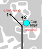
you need a 68PF disk capacitor on the wire going to the vco to help with the overload you are having. it buffers the signal going to the freq counter. it is not a resister as you mentioned. such as the grant LT I did it was not causing any problems going to the vco without the cap. so I did not use one.that is the center lead of the coax that has a ground wire on it. make sure you have the 3 wires going to the 8 volts at the front of the board that is only hot when you have it in either LSB, USB, and AM modes.when it is in say LSB mode the USB and AM mode wires are not hot. these hookups are coming off the band switch for each section..hope this helps you with it.

to check to see if the 100pf what ever you are using is causing the problem, unsolder it and see if it goes away when unhooked.

also make sure you did not splash any solder between any traces causing a short. look good in the area where you soldered the wires for 8 volts at each leg.
 
Last edited:
I unsoldered all of the wires this morning and the radio returned to peak performance and I am getting the static again. Seems for some reason some way that we had it hooked up was completely blanking out the receice which is extremely odd. I was picking up the local stations loud and clear and the counter was spot on frequency, but it just wasnt picking up the average everyday white noise.


Im sorry to bother you guys but can someone shed some light on exactly what the 68pf disk capacitor does, like its exact function in the hookup. Trying to understand if perhaps the 100pf I was using could have been the culprit of the lose of the receive power.
 
Also, Sonoma, I notice you mention three wires going to the bottom where the 8v USB,LSB and AM are...in the picture you posted I see the Orange which I know goes to the USB and yellow that goes to the LSB...but the other wire is brown which states that it is a ground wire. Does this wire still go to the AM? Or am i missing something?
 
wire numbers 3,4 5, 6 go to the lower portion of the board. the brown is ground. take a look at the layout again. try the red wire at a constant 8 volt sourch and see if it straightens out. hook each wire up and see which one is killing the receive. the vco pickup can kill receive if the cap is not right.

Galaxy DX Radios FC347 Wiring to SS3900
 
Last edited:
if you do not have a 68pf cap at the center coax lead that goes to the vco it will load the radio and make it act up. can lose receive or the freq counter will not work right. it can cause different problems. not sure how else to explain it since it never does the same thing every time.
 
just to second what sonoma is saying, you have confused to very different electronic components.
resistors are measured in ohms and limit current.
capacitors are measured in farads, and while they have many purposes, the one that matters in your application is that they will provide a means for connecting things so that RF can flow, but DC current and voltage cannot.

this is the important characteristic of capacitors here.
what you did was basically DC couple the freq counter to the VCO output, and by doing this you loaded down the circuit, vastly reducing its output.
that is why you saw such a lower receive gain.

you must use a capacitor here so that the freq counter can take a sample of the VCO output without putting any extra load on the VCO circuit.

it does not have to be exactly 68pF (picofarad) but should be somewhere in the range of 47-100pF. (i would go higher than 68 rather than lower if you cant find a 68pF cap)

you should be able to find a cap that will work in any junk radio.
LC
 
thanks LC and Robb. maybe this will help him. I told him to disconnect the wire at the vco and see if the receive came back but looks as if he unhooked all of it from the last post he made about it comming back on.
 
Does anybody have the EXACT needed hookup/setup for putting a Ranger FC-390 on a Uniden Grant XL to work properly please ???

73's Retro
 
Yes from what I'm gathering, 1 jumper inside the actual counter needs jumped, (seems to be the one near the crystal on top) and of course the proper hook up inside hard wired correctly. I'm not sure 100% if it is exactly as the FC-347 but signs point to it is !

Thanks for the reply, Retro
 
Okay so the Uniden Grant XL isn't any different ? You only do 1 jumper num 1 inside the FC-390 newer version freq counter I believe and hookup points inside is same as the FC-347 Sonoma ?

Good to know sir thanks, Retro
 

dxChat
Help Users
  • No one is chatting at the moment.
  • dxBot:
    Tucker442 has left the room.
  • @ BJ radionut:
    LIVE 10:00 AM EST :cool:
  • @ Charles Edwards:
    I'm looking for factory settings 1 through 59 for a AT 5555 n2 or AT500 M2 I only wrote down half the values feel like a idiot I need help will be appreciated