you will have to look inside the freq counter and see what board is in it.the info I left for you should show you each board number and how it looks. it has been years since I modded one of the newer boards.

You are using an out of date browser. It may not display this or other websites correctly.
You should upgrade or use an alternative browser.
You should upgrade or use an alternative browser.
-
You can now help support WorldwideDX when you shop on Amazon at no additional cost to you! Simply follow this Shop on Amazon link first and a portion of any purchase is sent to WorldwideDX to help with site costs.
-
A Winner has been chosen for the 2026 July 4th Retevis RA89R Giveaway! Click Here to see who won!
Adding Frequency Counter to Cobra 148 GTL with front panel mic.
- Thread starter 8113 Northern MN
- Start date

The Texas Ranger-brand FC390 in question has the latest "14D" board. You have to unsolder the pc board from the tin can, since the jumpers are on the side of the board facing down when you pop the top cover.
The stock setup meant for a Galaxy-type 10.695 MHz radio is both these jumpers open. That's what you'll find when you get the lower face of the pcb exposed.
The posted instructions at CB Tricks say to close both jumpers for a radio with a 7.8 MHz carrier frequency. Oddly enough, there are two other pairs of "jumper" pads on the board, but the instructions clearly show JP1 and JP2 only.
Closing them both brings about the fault in question on this radio. The displayed frequency is 2.5 kHz wrong.
First intuition would be a wrong setup on the orange and yellow wires. But it displays this error with both those wires unhooked, so that ain't it.
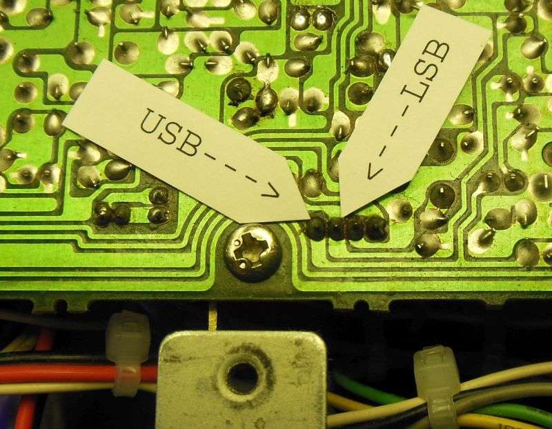
Besides, the USB/LSB offset when this counter has been set up for 7.8 MHz is +/- 1.5 kHz, NOT 2.5.... Proper function when it's set up for a Galaxy radio is up 2.5 kHz for LSB and down 2.5 kHz for USB. The 7.8 MHz radios use a 1.5 kHz up/down for SSB.
Anyway, here are the hookup points for those two wires on the pcb for a Uniden Grant XL. Foil-trace locations are the kind of tiny detail that changes a lot from one version of a radio to another. Can't remember the pcb number for this radio. Oops.
So, there's the puzzle. The J1/J2 issue suggest a possible error in the instructions, maybe?
One way to find out. The two jumpers offer us four possible combinations of open and closed. It came with both jumpers open. It now has both closed. The two remaining possibilities are J1 only closed and J2 open, OR J1 open and J2 only closed.
Just time and money to disassemble and try the remaining two possible combinations. Sure would be easier if it worked the way the instructions say it will.
Some days are like that.
73
The stock setup meant for a Galaxy-type 10.695 MHz radio is both these jumpers open. That's what you'll find when you get the lower face of the pcb exposed.
The posted instructions at CB Tricks say to close both jumpers for a radio with a 7.8 MHz carrier frequency. Oddly enough, there are two other pairs of "jumper" pads on the board, but the instructions clearly show JP1 and JP2 only.
Closing them both brings about the fault in question on this radio. The displayed frequency is 2.5 kHz wrong.
First intuition would be a wrong setup on the orange and yellow wires. But it displays this error with both those wires unhooked, so that ain't it.
Besides, the USB/LSB offset when this counter has been set up for 7.8 MHz is +/- 1.5 kHz, NOT 2.5.... Proper function when it's set up for a Galaxy radio is up 2.5 kHz for LSB and down 2.5 kHz for USB. The 7.8 MHz radios use a 1.5 kHz up/down for SSB.
Anyway, here are the hookup points for those two wires on the pcb for a Uniden Grant XL. Foil-trace locations are the kind of tiny detail that changes a lot from one version of a radio to another. Can't remember the pcb number for this radio. Oops.
So, there's the puzzle. The J1/J2 issue suggest a possible error in the instructions, maybe?
One way to find out. The two jumpers offer us four possible combinations of open and closed. It came with both jumpers open. It now has both closed. The two remaining possibilities are J1 only closed and J2 open, OR J1 open and J2 only closed.
Just time and money to disassemble and try the remaining two possible combinations. Sure would be easier if it worked the way the instructions say it will.
Some days are like that.
73
Tried two more of the "Texas Ranger" brand FC390, and all three of them respond the same way.
Same wacky symptom, reads 2.5 kHz low.
Clearly a "built-in" feature, not just a quirk in one oddball unit.
73
Same wacky symptom, reads 2.5 kHz low.
Clearly a "built-in" feature, not just a quirk in one oddball unit.
73
Well there has to be a way to get these FC-390's to work as Lester from Lescomm has done it and has videos on Youtube showing it. Darn frustrating now for me as I'm the one Nomad Radio is helping with them. Please someone out there ANY information related to this oddball cure reply here ASAP would be so much appriciated !
Guess Lester doesn't do forums, no clue but I'm going to ask him as I've bought from him a number of times so I figure he'll give some info that would knock this out for me...
Thanks in advance to ANYBODY that can clear up this mystery of sorts, Retro
Guess Lester doesn't do forums, no clue but I'm going to ask him as I've bought from him a number of times so I figure he'll give some info that would knock this out for me...
Thanks in advance to ANYBODY that can clear up this mystery of sorts, Retro
Again I'm using a Uniden Grant XL radio and need a FC-390 blue LED freq counter with the EPT210014D pcb to work on this radio reading correctly and NOT 2.5 khz low.
SOS folks - Retro
SOS folks - Retro
Ralph sells counters on ebay and his you hook the center coax wire to TP3 on the uniden grant XL. take a look at where you have it hooked up and try TP3 to see if it will work. I have never tried a 390 counter. I have always used the 347 which will read the counters as it should. I always just assumed the 390 was the same and just had the ranger name .
here is a link to the pic of the uniden grant LT radio. might help you
http://www.radiomods.co.nz/images_mods/grantltfc347freqcounterhookup.jpg
here is a link to the pic of the uniden grant LT radio. might help you
http://www.radiomods.co.nz/images_mods/grantltfc347freqcounterhookup.jpg
Last edited:
I have 4 of the fc390 counters and only one works on my grant XLs.......the only one that works properly was purchased with a grant and was already modded. I have went over that dam thing trying to figure out how they made it work and all I can tell is only the jp1 pad has been soldered...... frustrating!
here is a link to the mods of the counter fc347. it shows 2 different boards that was used in the 347 units. I have never did a 390 counter but a few guys have said it modded the same.one board has 1 jumper to solder and the 2nd board has 2 pads to jumper.
http://www.cbtricks.com/radios/galaxy/fc347/index.htm
http://www.cbtricks.com/radios/galaxy/fc347/index.htm
been there ....done that......doesn't work.here is a link to the mods of the counter fc347. it shows 2 different boards that was used in the 347 units. I have never did a 390 counter but a few guys have said it modded the same.one board has 1 jumper to solder and the 2nd board has 2 pads to jumper.
http://www.cbtricks.com/radios/galaxy/fc347/index.htm
I appreciate your input though....thank you.
maybe some close up pics of a 390 that doesn't work (both sides of the PC board) and some of the one that does work might help.
at least it would put more eyes with different skill sets on them. im not saying it's as simple as one is wired this way and one is wired that way, but pics certainly can't hurt.
the pics would need to be clear enough to be able to read the markings on the IC chips.
LC
at least it would put more eyes with different skill sets on them. im not saying it's as simple as one is wired this way and one is wired that way, but pics certainly can't hurt.
the pics would need to be clear enough to be able to read the markings on the IC chips.
LC
I know this is an old post, but whenever I come on here and I get help from you all I'm great full. I do my best to thank anyone who has helped me . It just kills me how much you guys helped him then poof he just disappeared into thin air without a "thank you for your time and effort"thanks LC and Robb. maybe this will help him. I told him to disconnect the wire at the vco and see if the receive came back but looks as if he unhooked all of it from the last post he made about it comming back on.
Ok, guys...
Remember, when in Rome, do as the Romans do.
Hint : CTRL+ALT+"+" from the PC AT/XT era...
Actually, it's CTRL+ALT+"-" from that same era...
Can't speed up the clock - it'll read lower on the gate - so the only way to have the "gate" count more of the cycles is to lengthen the gate cycle...
Meaning...
Slow the 4.5MHz clock down to a level showing the gated length of time in its count window - will show the new frequency "seems higher" why more sampling - slow the clock down - to raise the display frequency - speed it up to have the sample "gate" shorter and fewer "samples" get thru...
HINT: AGAIN - C18 and VC1
Or just compare 148F counter to the FC - you'll se the cap values are different...
Enjoy....
:+> Andy <+:
Last edited:
I think he is expecting to find a photo or diagram that exactly matches his particular board. I do not think he knows how to figure out, interpolate, extrapolate and test for those points on his own with tools.Not as meant as a slight against him either I am trying to explain what his actual issue is.He might not be used to thinking his way through a problem like one does when doing diagnostics and such. He might just be used to following known mod's as neatly laid out by other's. I hope I am not making anyone angry as I am trying to help explain what I think his problem is. A lot of us are used to just getting close then using test gear to narrow it down we are not always a slave to a diagram because we have all found out they are not always 100% accurate or you can not find the specific board you have but ou can find one that is close like the Realistic uPD858 boards versus the early Cobra uPD 858 board you can get close enough with either for most of the things you want to do and figure out the rest as you go but not everyone can do that.all you have to do is use a volt meter to check for the 3 wires that go for lsb am and usb 8 volts and then the vco area. it is all in the same location just the board layout looks a little different from one manufaturer to another. such as malaysia the taiwan then chains.. some of the traces change how they are shapped but still in the same area of the board. I do not have one like yours here to look at so someone will have to have one and wire it up for you to see.
that is what I did in about 2005 for a grant LT since everyone said it was different from the XL. Defpom's site has the pic of the LT. maybe it is the same as the cobra.
In fact I would say it is the difference between being able to plug and chug in math vs being able to think your way through a problem you have never seen before. Two completely different skill sets.
dxChat
- No one is chatting at the moment.