
You are using an out of date browser. It may not display this or other websites correctly.
You should upgrade or use an alternative browser.
You should upgrade or use an alternative browser.
-
You can now help support WorldwideDX when you shop on Amazon at no additional cost to you! Simply follow this Shop on Amazon link first and a portion of any purchase is sent to WorldwideDX to help with site costs.
Cobra 146 Frequency Mod For Switch Kit and Others
- Thread starter CollinsMan
- Start date
never seen it done that way before") ,
,
heres how i do it to get 80ch, no need to stretch clarifier range,
http://i5.photobucket.com/albums/y152/ukmudduck/ar144 stalker9 cobra146 mod/P1000696.jpg
,heres how i do it to get 80ch, no need to stretch clarifier range,
http://i5.photobucket.com/albums/y152/ukmudduck/ar144 stalker9 cobra146 mod/P1000696.jpg
Looks like a channel board Bob (and a nice one at that Nice radio to) Not like one I've seen before ? I know it's not the Expo N or Galaxy N , although I would take the Galaxy N over the Expo's crystals , although you only get uppers or lowers with the Galaxy N (not both) but you also don't have to mess with the clairifier range on those either or change the PLL .
The Expo N's always seemed very hard to stabelize on freq when I used them , but if you could make those work ? you got 40 up and 40 down out of those.
Nice radio to) Not like one I've seen before ? I know it's not the Expo N or Galaxy N , although I would take the Galaxy N over the Expo's crystals , although you only get uppers or lowers with the Galaxy N (not both) but you also don't have to mess with the clairifier range on those either or change the PLL . The Expo N's always seemed very hard to stabelize on freq when I used them , but if you could make those work ? you got 40 up and 40 down out of those.
I like that setup, Bob.... looks like an oscillator board with a can for each mode?
I have done the D2816 chipswitch mod for several years, and it works great! I do a couple things to the clarifier to make it slide the necessary amount, but maintain frequency stability.
I love the tech info, guys... keep it coming!
-Exit
I have done the D2816 chipswitch mod for several years, and it works great! I do a couple things to the clarifier to make it slide the necessary amount, but maintain frequency stability.
I love the tech info, guys... keep it coming!
-Exit
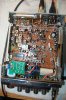
yes its an oscillator board, it started out life as the oscillator with one transformer for our legal fm band,
i removed all the parts and repopulated it with parts from scrap uniden/cobra exports,
the export cobra146 did it the same way with a much larger board, our first export version of the cobra 148 used an oscillator board for 3 bands,
it uses a transformer for each mode and a varactor for the clarifier, the main board has the holes ready to wire the board in so it looks factory standard,
the way others over here were doing extra bands on that type radio only allowed for one mode to be on frequency,
i used the same method in the early 80's to add two extra bands below 26.965 on the stalker st9fdx radios,
the one in the pic was the last ar144 i did years ago.
Well Bob , I really don't know about all that. But FM is basically not used here in the states (or at least not by me) I had asked AC the same questions I had asked you concerning this radio and the Galaxy N kit , well I figured it out , the directions were wrong unless the President AX-144 / Uniden AR-144 is slightly different from the Cobra 146 GTL ?
I've seen and been through variations of this board before , I believe the TRC-451 is also this chassis (Uniden made) the PC-122s and TRC-456s and TRC-453s are close but built somewhat differently. And the fact that they put mic gains on the AX and AR - 144s . These models are very solid and drift free on SSB which is a blessing. I have never been much on the chip switch on these radios , IM guessing ? that the chip switch is a older technology ?
I have never had much luck with Expo N Kits with there cyrstals , (they were always very hard for me to stabilize on freq) in the late 90s these Galaxy N Kits (blue box) came out with there two IC's , although they can be set for the lower freebands , higher freebands or even 10 meters ,with vco and down mixer adjustments, you can only have the choice of one. For me and SSB's radios , it's always the upper freebands from 27.425 to 28.045 I set them on.
The Galaxy N's are very stable channel kits with usuallly ease of installation. These kits will work in both AM and SSB type radios with many different pll styles.


I've seen and been through variations of this board before , I believe the TRC-451 is also this chassis (Uniden made) the PC-122s and TRC-456s and TRC-453s are close but built somewhat differently. And the fact that they put mic gains on the AX and AR - 144s
. These models are very solid and drift free on SSB which is a blessing. I have never been much on the chip switch on these radios , IM guessing ? that the chip switch is a older technology ? I have never had much luck with Expo N Kits with there cyrstals , (they were always very hard for me to stabilize on freq) in the late 90s these Galaxy N Kits (blue box) came out with there two IC's , although they can be set for the lower freebands , higher freebands or even 10 meters ,with vco and down mixer adjustments, you can only have the choice of one. For me and SSB's radios , it's always the upper freebands from 27.425 to 28.045 I set them on.
The Galaxy N's are very stable channel kits with usuallly ease of installation. These kits will work in both AM and SSB type radios with many different pll styles.
the destructions were not clear at all switch, neat little board, glad you got it going.
never seen the ax here, we had 40ch ar144's / 40 and 80ch 146's which were the same discounting the different front pannel,
some had the flo96 ssb filter and some had a folded piece of aluminum for extra heatsink bolted to the inside above the finals,
i remember doing something on an ax with a friend in australia a few years back and there were slight differences to what we had here,
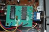
look at your driver bias, its adjusted fully one way, somebodys been twiddling
.never seen the ax here, we had 40ch ar144's / 40 and 80ch 146's which were the same discounting the different front pannel,
some had the flo96 ssb filter and some had a folded piece of aluminum for extra heatsink bolted to the inside above the finals,
i remember doing something on an ax with a friend in australia a few years back and there were slight differences to what we had here,
look at your driver bias, its adjusted fully one way, somebodys been twiddling
your right Bob , the instructions were not very good. Although after accomplishing this , they tend to make sence . I suppose it's just how things are explained that can make it so much harder for the person trying to accomplish the task. Or maybe it's just the way that are minds dysect things ? Thanks
Switch Kit
 i need inst. how to adjust the vco and down mixer . i have pc-122xl please or if you have the n kit instruction tx
This should help you Joe.
Channel Board For Cobra 146GTL & Uniden PC-122XL
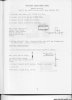
 Warning: The modification of the radio in the U.S. voids the FCC type acceptance and makes the equipment illegal! The installation of the circuit board is easy. The leads should be as short as possible. Locate the PC board as close to the 2824 PLL chip as possible. Either a SPDT center of toggle switch or a three position rotary switch can be used. If you buy a kit, it comes with the toggle switch mounted to the PC board. It can be removed or used to secure the board and switch in one step.
If you choose to build the PC board you can use a multipurpose PC board such as Radio Shack #276-150 or #276-159. Position all the components as close together as possible. Hand wire all connections using short wires. Mount the board securely and be sure that nothing metallic comes in contact with it including the speaker on bottom cover.
Once the PC board is installed and wired to the switch, four short wires need to be connected to the PLL circuit. First run a wire from the connection with the ground symbol on the expansion PC board to the can of L15. Next connect the lifted side of C67 to the (OUT) connection of the expansion board. Connect IC2 pin 10 to the expansion board connection marked (IN). Then connect IC2 pin 11 to the expansion board connection marked (+5 VOLTS).
To insure complete VCO coverage solder a 27pf capacitor across C72 on the back side of the radio circuit board. Make sure to lay it down flat and keep the leads short. Then double check your work looking for solder bridges and correct connections.
 CLICK ON PC BOARD LAYOUT FOR MAGNIFIED VIEW.
Next is the alignment procedure. Connect a watt meter, frequency counter and dummy load to the radio. 1) Put the radio in the AM mode on channel 1 with the expansion switch in the normal position and transmit. You should read 26.965 on the frequency counter. If the radio doesn't transmit, there may be a wiring mistake somewhere or the VCO may need adjustment. Adding the capacitor across C72 does change the adjustment slightly, but not usually enough to loss channel 1. If everything looks OK then melt the wax in L38 and adjust it slowly in either direction no more than 3/4 of a turn. You should now transmit on channel 1.
2) Put the expansion switch in one of the upper channel selections. and adjust L13 until you read either 27.285 or 27.605 on the frequency counter.
3) Put the expansion switch in the opposite expanded position and you should read the other frequency listed above. You should read 27.285 in one position and 27.605 in the other position. If not, tweak L13 a little until you do.
4) Check to see that you still read 26.965 in the normal position.
5) Switch to the position that yields 27.605 and switch the channel selector to channel 40. The counter should read 28.045. If it doesn't, melt the wax in L38 and slowly adjust it until you read the 28.045 on your counter.
6) Go back to normal channel I and insure that you read 26.965 on the counter.
If everything went well you have a radio that goes up to 28.045. Of coarse we know you will only receive these frequencies and never transmit above 27.405. Remember 28.000 is the beginning of 10 Meters.
I'm told for the Ham operators out there, moving the wire on the expander from pin 8 to pin 9 on the 7493 IC along with adjusting L13 and L38 will give you coverage in the novice portion.
Well, this article was supplied for information purposes and I hope you enjoyed it. Even if you don't tinker with radio equipment it's always good to be aware of what's available. Have fun!
Channel Board For Cobra 146GTL & Uniden PC-122XL
The Cobra 146GTL and Uniden PC- 122XL are low cost AM/S SB radios using a gPD2824 PLL chip. The Uniden PC-122XL is the same radio as the PC-122. They changed to the XL series when they went to the Cobra look front panels. Uniden also made the PRO-810e, a base radio with the same board as the 122. When this chassis initially came out there was no known way to add extras. This was viewed as just another challenge for the CB hackers and after a short while there were two methods of expanding coverage.
One uses two crystals that are switched into the tripler coil and this yields 40 extras above and below the center off position is regular 40, but it created a problem on sideband. This scheme rendered the clarifier inoperative in the expanded positions. A wire from the clarifier control to the expander kit was added to get some clarifier range but it was limited and all three modes had three different center slots. These kits also work on the Cobra 29-GTL and Uniden PC-76. These radios being AM only, work fine and these kits are the preferred method of expansion.
The other kit doesn't use crystals. It uses two ICs that generate a signal for the tripler coil in the PLL circuit. The clarifier works the same in all positions of the expansion switch. This makes for ease of operation. The only drawback is the total channel coverage is reduced. It doesn't yield any lower frequencies but it does make the radio cover up to 28.045 Mhz.
If you choose to build the PC board you can use a multipurpose PC board such as Radio Shack #276-150 or #276-159. Position all the components as close together as possible. Hand wire all connections using short wires. Mount the board securely and be sure that nothing metallic comes in contact with it including the speaker on bottom cover.
Once the PC board is installed and wired to the switch, four short wires need to be connected to the PLL circuit. First run a wire from the connection with the ground symbol on the expansion PC board to the can of L15. Next connect the lifted side of C67 to the (OUT) connection of the expansion board. Connect IC2 pin 10 to the expansion board connection marked (IN). Then connect IC2 pin 11 to the expansion board connection marked (+5 VOLTS).
To insure complete VCO coverage solder a 27pf capacitor across C72 on the back side of the radio circuit board. Make sure to lay it down flat and keep the leads short. Then double check your work looking for solder bridges and correct connections.
CLICK ON PC BOARD LAYOUT FOR MAGNIFIED VIEW.Next is the alignment procedure. Connect a watt meter, frequency counter and dummy load to the radio. 1) Put the radio in the AM mode on channel 1 with the expansion switch in the normal position and transmit. You should read 26.965 on the frequency counter. If the radio doesn't transmit, there may be a wiring mistake somewhere or the VCO may need adjustment. Adding the capacitor across C72 does change the adjustment slightly, but not usually enough to loss channel 1. If everything looks OK then melt the wax in L38 and adjust it slowly in either direction no more than 3/4 of a turn. You should now transmit on channel 1.
2) Put the expansion switch in one of the upper channel selections. and adjust L13 until you read either 27.285 or 27.605 on the frequency counter.
3) Put the expansion switch in the opposite expanded position and you should read the other frequency listed above. You should read 27.285 in one position and 27.605 in the other position. If not, tweak L13 a little until you do.
4) Check to see that you still read 26.965 in the normal position.
5) Switch to the position that yields 27.605 and switch the channel selector to channel 40. The counter should read 28.045. If it doesn't, melt the wax in L38 and slowly adjust it until you read the 28.045 on your counter.
6) Go back to normal channel I and insure that you read 26.965 on the counter.
If everything went well you have a radio that goes up to 28.045. Of coarse we know you will only receive these frequencies and never transmit above 27.405. Remember 28.000 is the beginning of 10 Meters.
I'm told for the Ham operators out there, moving the wire on the expander from pin 8 to pin 9 on the 7493 IC along with adjusting L13 and L38 will give you coverage in the novice portion.
Well, this article was supplied for information purposes and I hope you enjoyed it. Even if you don't tinker with radio equipment it's always good to be aware of what's available. Have fun!
down mixer on the 122 is L38 / vco is L13 ........slow and easy goes it on those Jose. Hope all that helps you amigo.
thank you Switch kit for all the great information this is not easy i messed up L13,L14 and L38 sometimes i am on the ball game on channel 1 on all three postions but channel 40 is off anyways it justs a hobby ill keep trying
Attachments
You just need to take your time with those , they can be touchy to lock in when first installed (if that's what your doing ?). A good idea is to let the radio warm up for a hour or so before you start . Then just follow the directions as above. You really need to go turtle slow with 13 and 38 , the freq's will drop in , like I said , you can either set them for the higher bands or lower bands , you'll see them pop in on your freq counter.
You may only get 1 set at a time , that's OK , you just slowly go back to work on 38 and 13 , once you see that you got them locked in , put the wax back into 13 and 38 then let the radio sit on for a few hours. You should be good to go there after . Did you use the 27pf cap over C-72 ? This can really help with stability on freq ? I've been able to set them with out the cap at times , but most of the time the cap is a plus for locking freqs' in .

You may only get 1 set at a time , that's OK , you just slowly go back to work on 38 and 13 , once you see that you got them locked in , put the wax back into 13 and 38 then let the radio sit on for a few hours. You should be good to go there after . Did you use the 27pf cap over C-72 ? This can really help with stability on freq ? I've been able to set them with out the cap at times , but most of the time the cap is a plus for locking freqs' in .

dxChat
- No one is chatting at the moment.
-
-
-
dxBot:63Sprint has left the room.
-
dxBot:kennyjames 0151 has left the room.
-