• You can now help support WorldwideDX when you shop on Amazon at no additional cost to you! Simply follow this Shop on Amazon link first and a portion of any purchase is sent to WorldwideDX to help with site costs.

cobra 148 unlock PLL

Ok, slow down! Condition of Pin 6 on PLL? Are we in lock or...???

Could be something as simple as you need to do a continuity check from D31 backside to R163 and from Backside of D43 ---

Now, back to D31 check foil trace to...D43.

Remember at the PLL - is a helper for the "pull up" on the PLL LOCK sense line from + side of C84 to D31 "UN-banded end" , it should show 22K.

Then on D31 UNBANDED side, to D43 UNBANDED side - show good continuity...
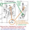
5pinwiring.jpg

You may need to re-check the Microphone Pin 4 THRU PIN 3 (Shows ground) as a continuity check FROM THE HANDSET - as in the Mic plunger switch - to TR35 to verify that even the CB / PA switch is wired correctly...

Do the same for Pin 4 to 5 on TX.

TR35 may give you a bad reading see Nomads' reply below...

Did this graphic earlier in the day - updated pinout ... sorry about that folks...
 
Last edited:
Check the base of TR35. If you have 8 Volts more or less, TR35 is bad.

If you have around 1 Volt or two, move upstream to D43. The "Locked only" 8 Volt source feeds into it. You should have about 8 Volts DC on the anode (not banded) end, and about 6/10 of a Volt less on the cathode end.

If the anode end voltage is low, D43 is not the roadblock. Check D31, near the 8719 PLL chip. Should have about 8 Volts on both sides. The cathode is connected to pin 6 of the PLL chip, the lock-detect pin. If it's much lower than that on the cathode (band) end, the PLL is not fully locked. This pin may oscillate between 8 Volts and ground if the PLL is only marginally locked in.

A 'scope will reveal this at a glance. When this happens it will cause a DC meter to read some random value under 8 Volts on pin 6 of the 8719.

73
 
ok ic1 pin 6 0.0v. d31 anode to r163 and d43 yes continuity check.+c84 to anode d31 i have 22k.now from ground to E OF TR35 PRESS PTT and i have continuity. but what i see C of tr35 always on 13.8v and r162 not switching on both ends have 13.8v. Base of tr35 i have 1.2v .I do NOT have 8.0v on pin 6.pll is not locked. HUMMM 73'S.
 
Last edited:
Ok, now leave MB3756 alone for now...

You got that done...

Now, go back to the start of these posts again - you showed Pin 5 and Pin 6 of PLL - we got the RX and TX switch the moment you were able to make it toggle by ground Pin 5.

We needed to verify the Mic was wired correctly...Pin 3 to 4 handles RX for Speaker Ground and Pin 5 ground to Pin 3 then you TX - we needed to verify you have the mic wired right...

When you lose lock, it makes PLL pin 6 low - that affects the RX by muting the Audio Amp chip using TR47 and TR53...

So with RX quiet - no RX at all - lets' fix Pin 6 of the PLL...

Adding a little more...

I can appreciate that you have the resources to replace a lot of parts, so I guess I need to step aback a moment and say WHOA!

We don't want a ton of parts replace, I'm asking you to check them - make sure there are voltages on them when that radio is on, the RX to TX and Back again - should show something - but I do understand the PLL 6 is low - things don't work we need them to so verify that the caps are not shorted or the diode blown - it can't work right - if something as simple as a bad mic cord - blows everything out of the water if the obvious isn't checked first...
 
Last edited:
  • Like
Reactions: Robalo and Rwb
PLL MB 8719
PIN 1 = 6.56V
PIN 2 = 3.29V
PIN 3 = 0.0V
PIN 4 = 8.27V
PIN 5 = 8.27V
PIN 6 = 0.16V
PIN 7 = 4.46V
PIN 8 = 4.40V
PIN 9 = 8.31V
PIN 17 = 3.58V


Rob and I live in the Silicon Valley and we go to electronic outlet stores, so we have a lot of parts... Right Rob? 73's
 
Last edited:
Robalo:

You need to see if the PLL PROGRAMMING is ok too. Are all pins programming right?

PLL MB 8719
PIN 1 = 6.56V
PIN 2 = 3.29V
PIN 3 = 0.0V
PIN 4 = 8.27V
PIN 5 = 8.27V
PIN 6 = 0.16V
PIN 7 = 4.46V
PIN 8 = 4.40V
PIN 9 = 8.31V
PIN 17 = 3.58V
The wrong program can tell the PLL to stay off by Pin 6 being low, meaning the channel selector should be checked too - sounds obvious but if the darn things been dropped you get broken wafers inside it...

See Below...
PLLMB8719Pin6BCD1.jpg

You can check all the stuff and things seem ok, but if Channel Selector it trying to fool PLL - Pin 6 turns off - all bets are off.

Verify D31 and D43 are not shorted - so they don't intentionally cause a false positive or even prevent lock by sucking current out of the circuit. (like a bad TR35 in RX can cause quirky results)

Pin 6 should also be "live" but that doesn't equate to the VCO LOCK line being set right, so verify that the ROM and BCD Channel selector are lining up right - and that the Pin 6 Detent from the Channel Selector is not pulling the line low because of physical damage to the selector.

Worse case scenario? PLL may have blown Pin 6 internally - being low CONTANTLY now because of the internal switch is now a melted chip of metal...You can always lift D31 to let the radio work and see if this is the problem.

That's for later ok? WAY DOWN THE LINE...Focus of the BCD and Pin 6 loopback from the Channel selector.

Had to lift D31 before to see if any of the channel selector pins could even get the thing to work and make the ROM turn on the PLL chip - if you get certain channels to work but not all replace the Channel Selector and try again...
 
  • Like
Reactions: Rwb
D43 removed no change no voltage on E-B OF TR35 put it back, lift anode of D31 now I have 8.3v on JP40 to S401 before no voltage, when I press mic ptt red led comes on good tr35 switching but pll same numbers. I have microchip socket on IC1 and I have 3 new MB8719 switching back and forth on same voltage from pin 1 to pin 9, So it is not the microchip. This stuff is fun isn't it?

getting close
 
  • Like
Reactions: Rwb
Ok, thanks for doing that - had a NOS radio that at the time knew little about internal damage - found out the radio suffered from a Faceplant - pushing the channel selector knob in against a stop - the detent would work as far as ratchet and channel display - but the line stayed high all the time - acting like the Squelch was on and that knob / control was replaced and pot showed fine out of circuit...It's then when I noticed the Channel knob was "popped" on the front - the shaft was popping thru the stopper part of the plastic...

But we need to get to the Truth - does the channel selector follow the truth table?

Why this step?
ift anode of D31 now I have 8.3v on JP40 to S401 before no voltage, when I press mic ptt red led comes on good tr35 switching but pll same numbers. I have microchip socket on IC1 and I have 3 new MB8719 switching back and forth on same voltage from pin 1 to pin 9,

The only thing we haven't done - is make sure the pin programming is correct - no matter which PLL chip we put in there - the thing won't allow us to continue unless there is some truth to the truth chart...AKA - Pin 6 will always be low if ROM and pins don't match.

But thanks for the D31 - this means we are all set to continue - keep the "D31" thing in mind to help determine if Pin 6 is held low for EXTERNAL TO THE PLL reasons - failed cap, static poke on TR35 - stuff like that...let's us know the switching circuit works...then you didn't have to replace all those parts..

C80 and C81 are always problematic, part of the charge pump - have you replaced these yet.?

Crazy...how's TP 10? Scope the wave - wonder wandering now...Thinking UHIC-007 - but first - let's see if the PLL can work with that Tripler... TP10 first...

Don't Panic...

NEWER148UHICReplacement.jpg

You can also scope TP 9 and see what is to become of the PLL 's attempts at trying to ramp a voltage to make the Varactor inside the UHIC work...this can also indicate the condition of the low-pass / smoothing / slope filter using C90 R104 and C91 (0.01uF Disc) - spikes indicate cap C90 may need replacement...or if too low - C90 is gone - replace...C92 is also part of the "gastric bypass" the internal mixing amp uses to obtain gain at the cost of bandwidth.

You can also see the use of the two comparators arranged as a free running high-speed and low-speed oscillator - using the loop from TP9 - including the Charge Pump that raises the Varactors' bias voltage...
I went searching for something that helps us understand that UHIC chip - this is from a 148F - so at least you have an idea of the internal workings...

I've got the above from the downloads.cobra site...PDF also included...

I'll let you wander about the schematic in hopes that the PLL design can inspire some extra ommph into solving your situation - I always enjoyed contemplating a drawing like the above - especially during moments of stress and the need to go to the bathroom - I find a lot of inspiration in using this method to get thru a blockage...
 

Attachments

  • 148GTLschematiclateversion.pdf
    499 KB · Views: 22
  • Like
Reactions: Rwb
i've been checking and reviewing all the posts and what you've been asking me to do and basically it has a lot of new parts but they are not working as its supposed to be. Reading some books looking at the diagram you sent me, id like to ask you if its a good idea to test the vco circuit by applying a dc clamping voltage so i can adjust L19 on channel 40 am for 3.2 volts. I think the best way to do that is remove R207 and apply 8.2 volts to see what happens. do you guys think that's right? I've been looking information on truth chart how to make those kind of tests. 73
 
  • Like
Reactions: Rwb
IF you can physically wire channel 19 to the pins of the MB8719 - that would be a great starter of known frequency and channel - skipping/bypassing the channel selector to keep it simple while you check. I'd think it's worth a try - at least you'd know the pins were set ... just yank out the channel selector and recheck it later...You can remove several lines of data sensing the PLL does to make sure the externals are correct before it goes to a frequency.

You said it had mods in it. have they been completely removed? The voltage regulator the MB3756 chip is one of the first things to have to take the heat or power loading of these mods. So it sounds like you've replaced it - we're done there - - - let's continue...

I asked earlier about Continuity Checks - because if someone wanted to hear themselves - the first thing they'd want to do is somehow put in a speaker to hear themselves (sounds narcissistic but work with me here :)) So if the PA CB switch is funky - there's part of the ballgame that ain't gonna let the radio work...

Was there work to the RX/TX light? That too is an indicator of a condition of how well the radio is willing to work. No green light - it still ain't right... No Red light - we're in for a fight... (Cheering section)

Ok, sent the cheerleaders home...

The tuning voltage would be 3.2V or thereabout. You can damage the UHIC chip if too much power is applied. It's going to a base thru a cap internally in the chip, but it's Varactor is directly hooked up thru a buffer resistor - not a divider - a buffer to limit current but not breakdown voltages. It's just so it's sees a high impedance voltage presence - just no power behind it - to make the L19 tank resonate - L19 is just a resonating tank for the Varactor.

Just we are not sure of the condition of the Varactor - but if the radio is NOS - then I'm suspecting more of an issue with aging parts, not too many miles on old caps usually is my first go-to, to replace.

Can you get 34 MHz in from the tripler?

6.8V is starting voltage to try and make UHIC chip start to clock - but if the support circuity like the Xtal (10.240) isn't firing - that's one set of problems. It seems the chip is missing parts or portions of the oscillator inputs to "clock" against.
 
Last edited:
  • Like
Reactions: Rwb and Robb

dxChat
Help Users
  • No one is chatting at the moment.
  • @ Wildcat27:
    Hello I have a old school 2950 receives great on all modes and transmits great on AM but no transmit on SSB. Does anyone have any idea?
  • @ ButtFuzz:
    Good evening from Sunny Salem! What’s shaking?
  • dxBot:
    63Sprint has left the room.
  • dxBot:
    kennyjames 0151 has left the room.