
You are using an out of date browser. It may not display this or other websites correctly.
You should upgrade or use an alternative browser.
You should upgrade or use an alternative browser.
-
You can now help support WorldwideDX when you shop on Amazon at no additional cost to you! Simply follow this Shop on Amazon link first and a portion of any purchase is sent to WorldwideDX to help with site costs.
-
A Winner has been chosen for the 2026 July 4th Retevis RA89R Giveaway! Click Here to see who won!
cobra 148 unlock PLL
- Thread starter Robalo
- Start date

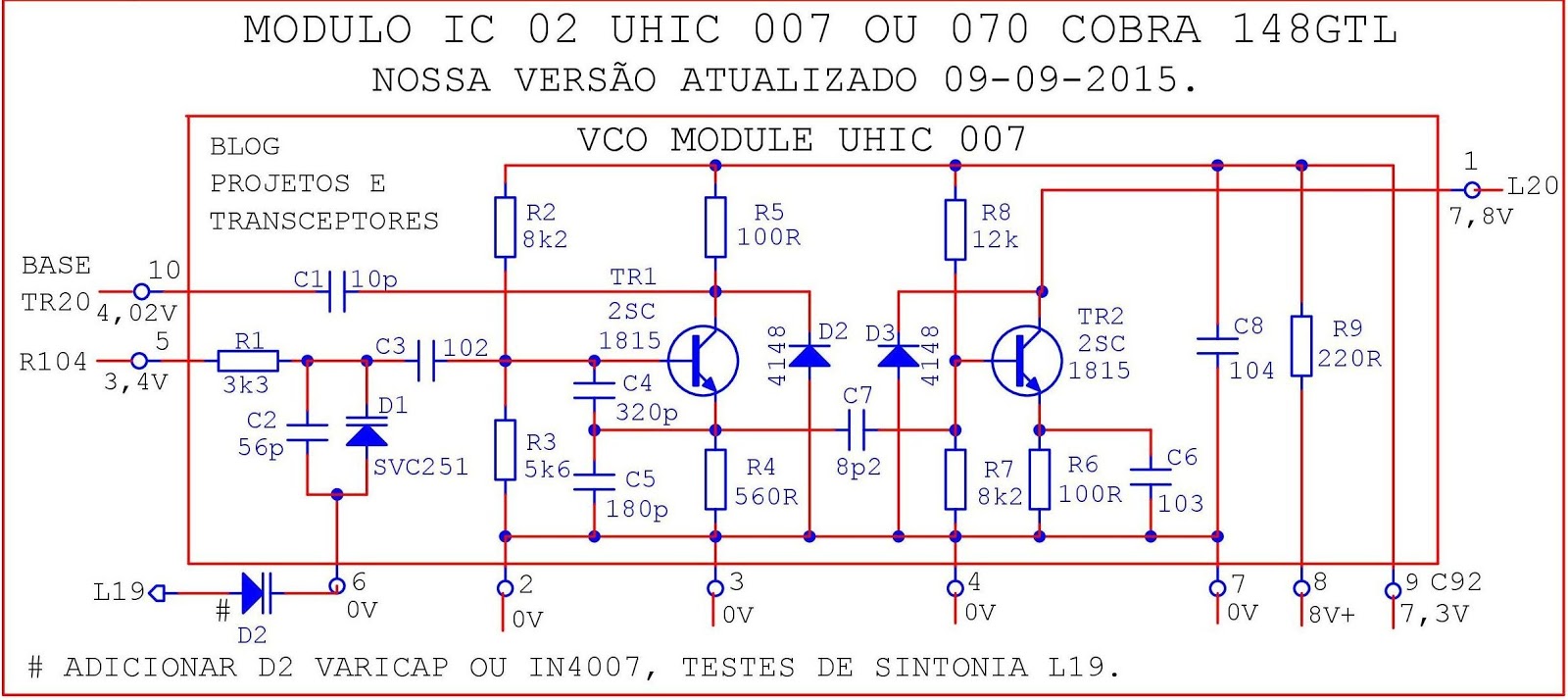
Have you ever considered putting a capacitor, say, 47pf, across pins 5 and 6 in order to broadband it?
The UHIC007 is one of those "never goes bad" parts.
Of course, there's no such thing as a fail-proof component. But it would be incredibly rare to see one of these go bad. Probably the most-dependable component in the radio.
HOW CAN I TEST IT OUT OF RADIO ?
About the only thing you can check for is to see if there is open or short across pins. Remember that the GROUND to Positive Power - has polarity to prevent reverse - bias - but when you test, you can't "See" if the varactor even works.
You may be able to test the diode status but not it's quality by doing an ohmic check between Pin 5 and 6 should only show a resistance one way infinite on the other...
So It would be better to swap out a known good UHIC into this but ONLY AFTER VERIFIYING THE VOLTAGES ON THE PINOUT SHOWN ABOVE are what you get in your radio - as per - in your diagram.
The Twin-Varactor shown in the Pin 5 output - would provide LESS slide than to use what is already there.
Series capacitance divides down like Paralled resistance - less than the lowest value used in the circuit.
couldn't find it in the thread, but has D31 been lifted and then TX tested to determine whether or not the problem is in the lock detector or the PLL?
have pins 6 and 8 on the voltage reg been lifted from the board and determined that they are switching correctly?
is the voice lock going to be put back to stock or is it going to run on RX and TX?
LC
have pins 6 and 8 on the voltage reg been lifted from the board and determined that they are switching correctly?
is the voice lock going to be put back to stock or is it going to run on RX and TX?
LC
You can manually ground pin 5 of the MB 3756 to Foil ground and see if TX comes on. YES IT DOES TX good.
Give L20 about a turn and a half clockwise, see if that locks it in. Looks like it's spun out too far. Give that a try and let us know how you get on.
~Cheers~
NO DOES NOT. thank you.
now pin 5 from mike run red wire to cb/pa and green wire to tr35 and when i press ptt beeep to ground good now i goint to vr5 r187 i have good ground but running to r188 i have no 8.0 v ok now check ic4 pin 8 press ptt (0.22v at the pin and 0.66v at pc board) no voltage ok so bad voltage regulator i hope. also i remove d31 and i have on tr35 C 13.9V BASE 8.3V AND E 8.3V . ok new ic4 and no 8.0v on tx. on pin 8 so what else could be.
thank you Exit13,Robb and Handy Andy to open my eyes.lol 73's
So D31 was checked via grounding Mic wire the one that goes thru CB/PA switch and toggled on.
So that leaves the PLL or the 11.325 stuff - and we have to see if 8 volts gets there...
Robalo:
Locate R143 (220ohm) and look for 8V ALL THE TIME.
Locate R149 (10K) One side has Clarifier voltage in RX and TX other end is ground.
Locate L60 See if you have Clarifier Voltages in RX and TX there too.
IF you only have Clarifier in RX - fix D75 and D52 so you can get TX back so the Varactors have something to work with.
D75 and D52 are buffered with R188 (100 ohm) and R187 (2.7K) so you'll have close to 6V on the TX side or clarifier voltage to work with. VR5 is a 3K I hope it's still in there - some take that part out to remove the TX side altogether.

Last edited:
R143 AT J31 AND R139 8.32V AND AT C OF TR30 7.97V
R149 ONE SIZE IS GROUND AND THE OTHER END HAS 5.1V
L60 5.1V AT TWO LEGS .TESTED OUT 0.52MH 4.2 OHMS.
CATHODE D52 5.V D75 NO VOLTAGE,VR5 IS THERE AND R188 IS LOW V
VCO TESTED OUT PIN 5 (-) 6 (+) READ 1.8 INFINITE ON THE OTHER.
NITE,NITE 73'S
R149 ONE SIZE IS GROUND AND THE OTHER END HAS 5.1V
L60 5.1V AT TWO LEGS .TESTED OUT 0.52MH 4.2 OHMS.
CATHODE D52 5.V D75 NO VOLTAGE,VR5 IS THERE AND R188 IS LOW V
VCO TESTED OUT PIN 5 (-) 6 (+) READ 1.8 INFINITE ON THE OTHER.
NITE,NITE 73'S
Ok! Thanks .... Hope these voltages you posted are on your TX side...
Your issue may be with TX voltage as you wanted to convert to stock.
If TX voltage fails - you have no BFO available at TR20 - so the PLL goes OUT OF LOCK. (Doesn't mean you lose 35MHz) - just its not BFO'd with TR20 to obtain an output for PLL to divide by...Pin 17 (Fin) this may also mean L19 is funky... part of the tank circuit to peak VCO.
Then try to retune - looking at TP10 - thru L19 (Turn on bandwidth filter an look for 1MHz signal as you tune L19) - and DVM TP9 - then look for output on TP1
So you may need to check PLL Pin 6 in ALL MODES and RX and TX - but get Clarifier back to stock first.
R188 low, it should have 8V TX - it's only a 100 ohm buffer resistor...
R187 one side will show voltage - other side to ground (no voltage) and it's value is 2.7K.
At the output of WIPER on VR 5 - the WHITE wire RX voltage goes to hole just in front of it - and BACK BEHIND D75 D52 mess - thru D 51 merges with Wiper out of VR5. There should be a 3 pin header for it back behind the open area - but if removed, the two outer holes board front facing you - Left Hole - return, Center Wiper, Right hole - TO clarifier for power (input)
Right now, on RX you see 5~6 volts for Clarifier - that's about right for this design. TX lines up the same...so if it "falls" you have to back track to the MB3756 - and quickest indication is red TX light. No light - no lock - so you may have to key it up manually as you did before to "prove" RED LED light does indicate (turns on).
His big concern was to get 35MHz into pin 17 does not help the situation so he thinking one of the two pass filters is out - just not sure - C88 and C89 are supposed to remove the 35MHz stuff to leave behind 2MHz (The major fundamental of TR20) for the Fin pin. the 0.022uF can get flakey too...
Your issue may be with TX voltage as you wanted to convert to stock.
If TX voltage fails - you have no BFO available at TR20 - so the PLL goes OUT OF LOCK. (Doesn't mean you lose 35MHz) - just its not BFO'd with TR20 to obtain an output for PLL to divide by...Pin 17 (Fin) this may also mean L19 is funky... part of the tank circuit to peak VCO.
On a separate note, talked to a friend about the PLL issues of losing lock - he says its a common problem but usually with the design they've gone and redone - L16 and L17 - you shouldn't have even got a 35MHz signal thru all that - so they think you have a bigger problem with the UHIC chip which seems to circle back to what you originally thought. Don't give up though.
May also indicate a coil has opened (turned into a cap) but you'd have no power output on TR20
May also indicate a coil has opened (turned into a cap) but you'd have no power output on TR20
Then try to retune - looking at TP10 - thru L19 (Turn on bandwidth filter an look for 1MHz signal as you tune L19) - and DVM TP9 - then look for output on TP1
So you may need to check PLL Pin 6 in ALL MODES and RX and TX - but get Clarifier back to stock first.
R188 low, it should have 8V TX - it's only a 100 ohm buffer resistor...
R187 one side will show voltage - other side to ground (no voltage) and it's value is 2.7K.
At the output of WIPER on VR 5 - the WHITE wire RX voltage goes to hole just in front of it - and BACK BEHIND D75 D52 mess - thru D 51 merges with Wiper out of VR5. There should be a 3 pin header for it back behind the open area - but if removed, the two outer holes board front facing you - Left Hole - return, Center Wiper, Right hole - TO clarifier for power (input)
Right now, on RX you see 5~6 volts for Clarifier - that's about right for this design. TX lines up the same...so if it "falls" you have to back track to the MB3756 - and quickest indication is red TX light. No light - no lock - so you may have to key it up manually as you did before to "prove" RED LED light does indicate (turns on).
His big concern was to get 35MHz into pin 17 does not help the situation so he thinking one of the two pass filters is out - just not sure - C88 and C89 are supposed to remove the 35MHz stuff to leave behind 2MHz (The major fundamental of TR20) for the Fin pin. the 0.022uF can get flakey too...
Last edited:

This is related to the PLL MB8719...
Make sure Pin 10 is/remains open.
Why?
I have a hunch (unnamed source) that the chips - some may not have had validated ROM programming. You may find several dead ones until you find a good one that the ROM programming did take.
DO THIS METHOD BELOW ONLY IF YOU CANNOT MAKE THAT PLL CHIP WORK NO MATTER THAT TYPE OF TUNING OF L19 or L20 you can do - shows Pin 6 low - Out Of Lock....You have nothing left to lose...
IF you find the PLL appears dead - ground Pin 10 - try again.
Rotate you channel selector - try various channels and tweak L19 and L20 as a means to see if you can lock it in - it may not be a channel or a frequency on the standard 40.
Still dead?
Pull up Pin 10 with a 22K resistor jumped to Pin 9 (8VDC) - try again.
Why these steps - to verify the PLL programming ROM...
IF the pin toggled low or toggled high makes the PLL "Appear" to work - no matter what pins P1 to P6 pins are set - you won't be able to get a channel in right because the "Mask" used to program the ROM into the chip was bad (or for a different radio). Pin 10 is a force carry in and develops a frequency divided 128/N type of thing - means it will work out of Band - but you'll need to use a Channel Selector from a Cobra DX or Grant DX models - the wafer program is different to match the ROM Mask internally.
Attachments
Last edited:

That's embossed plastic - yikes - may be fakes - Original Mitsubishis were silkscreens...
Like the Fujitsu shown above...
Like the Fujitsu shown above...
dxChat
- No one is chatting at the moment.
