You are using an out of date browser. It may not display this or other websites correctly.
You should upgrade or use an alternative browser.
You should upgrade or use an alternative browser.
-
You can now help support WorldwideDX when you shop on Amazon at no additional cost to you! Simply follow this Shop on Amazon link first and a portion of any purchase is sent to WorldwideDX to help with site costs.
-
A Winner has been selected for the 2025 Radioddity Cyber Monday giveaway! Click Here to see who won!
Cobra 2000 GTL ideas...
- Thread starter Cable Guy
- Start date
Back in the bad old (good?) days when a straight 2 or four transistor "box" could be had for a modest sum the opportunity arose for some so obvious it isn't even clever additions.
The easiest was pick up a pair of Cobra 2000 external speakers, put a good supply in one of them and the amplifier in the other. Nothing fancy, just a 100-200 watt upgrade.
The second was digital synthesizers were beginning to appear and be somewhat reliable. A true Digital VFO was a possibility.
Fast forward to today and an SDR sniffing your IF to give a waterfall display of or at your current frequency are nearly plug and play.
Actually the common RTLSDR usb dongle and a RasPi would be enough save for the lag.
But

And something like that amp mentioned above. *
And
Leave the 2000 alone. A massive overhaul and modification just isn't worth it. Unless it is.
Just a thought.
*Note" the Radioberry output although a fully formed signal is only on the order of 20-30mw. Then the PA will need a band pass filter. YMMV
The easiest was pick up a pair of Cobra 2000 external speakers, put a good supply in one of them and the amplifier in the other. Nothing fancy, just a 100-200 watt upgrade.
The second was digital synthesizers were beginning to appear and be somewhat reliable. A true Digital VFO was a possibility.
Fast forward to today and an SDR sniffing your IF to give a waterfall display of or at your current frequency are nearly plug and play.
Actually the common RTLSDR usb dongle and a RasPi would be enough save for the lag.
But

And something like that amp mentioned above. *
And
Leave the 2000 alone. A massive overhaul and modification just isn't worth it. Unless it is.
Just a thought.
*Note" the Radioberry output although a fully formed signal is only on the order of 20-30mw. Then the PA will need a band pass filter. YMMV
Kopcicle, I've come to the conclusion that even though I get bored and look fondly on the ways to mangle a classic into something of my own wild imagination, going against the grain to leave my mark on the world, or a few radios, I just can't bring myself to commit sacrilege. Rest easy, ole boy, she's gonna stay stock, I'm even considering putting the limiter back in (which I did not remove btw).
I think it's the same, the board is upside-down in the top picture. I bought one too, hopefully it will work when I put it together.CHRIS -
I checked out the link you posted. The ad shows 2 different amps in the same ad
This amp is the one shown in the top pic on the left
View attachment 71034
AND this is the ampkit shown in the 2nd photo on the left
View attachment 71035
I ordered one kit. I wonder which one i will get ??The 2nd one I hope
- J.J.399
Sorry J.J., I for got about that previous post in this thread. Carry on.J.J. I think you're in the wrong thread bud.
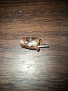
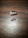
Hey, Nomad, let me pick your brain. I just remembered, when I first opened this radio, this was floating around in there and fell out.


Looks like a diode, but I couldn't find where it used to live. The radio works fine now as far as I can tell. Maybe the cause of tr302 failing.
Do you remember seeing a diode with a plastic/rubber sleeve in these Taiwan models? If so, do you remember roughly where? It could have been added after manufacture, maybe a mod. It looks like it got hot enough to unsolder itself. Since it was enclosed in a sleeve, I'm guessing it populated the solder side of the board. I'm not terribly worried, but if it has a darn good purpose, I'd darn well like to know about it.
Thanks and Happy Thanksgiving Day!
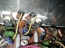
This radio has had the driver and final replaced at some point, but they used a NTE235 driver and a NTE236 final.
As I understand it, those could be original 2166/1969 mitsubishi trans under that NTE print, but could also be some "close enough" equivalent they could buy up cheap at the time.
I have some legit 2166/1969 trans, should I change them?
As I understand it, those could be original 2166/1969 mitsubishi trans under that NTE print, but could also be some "close enough" equivalent they could buy up cheap at the time.
I have some legit 2166/1969 trans, should I change them?
Attachments
If it ain't broke don't fix it.should I change them?
Always remember the rule of the shade-tree mechanic. "If it ain't broke keep fixing it until it is."
73
Well, not broke really, you got me there. A little weak, yeah. I can usually get 16-18 watts out of this chassis easy, when stock mitsu. bipolars are used. These are topping out at 10 watts AM/SSB pep, leading me to believe it could be better. Maybe these are the "close enough" trans, and I have to figure out how they like to be stroked, er uh, biased, tweaked to give better performance. Now, I don't worship my meter, and those last few watts won't keep me awake at night, but if the speed limit is 55 mph, I prefer driving 55.If it ain't broke don't fix it.
Well of course!Always remember the rule of the shade-tree mechanic. "If it ain't broke keep fixing it until it is."
Easy way to tell a Mitsubishi-made 1969 or 2166 is the width. The real thing is 9mm across. All other "TO-220" metal-tab transistors are 10 mm. Your '236 final looks to have started out life with 2SC1969 marked on it before being remarked. Odds are the driver was a 2SC1306 when it was born. That number didn't get discontinued as soon as the big brother 2SC1307. For a few years the '8719-based SSB radios used a 1306 driver and 1969 final. Some time in the 1980s they changed over from the 1306 to the 2SC2166.
Two things to check if one of those radios has anemic transmitter power. First, make sure that all the 10mm slug-tuned coils in the transmit chain show a peak with the slug below the rim of the hole in the top of the can. Any of them that appear to show a peak with the slug DEAD EVEN with the rim of the hole isn't really a peak. That can has a failed internal capacitor. That 'flush' position of the slug is where the inductance maxes out. That slug has reached the end of its travel before actually reaching a true resonant peak. This will reduce either receiver sensitivity or transmit power, depending on where that can is placed.
Second is the slug inside L38, the fat coil that feeds out of the final transistor. If L38 peaks with the slug nearly bottomed out, something is out of whack. Just doesn't tell you what. Should peak with the slug a turn or two below the rim. This one maxes its inductance with the slug all the way down.
Naturally the power-supply voltage should be right on the 13.5 to 13.8-Volt range.
And if you 're getting 16 or 18 Watt peaks, put a nail in it. Job's done.
73
Thanks Nomad, I learned that slug thing on here years ago, it's second nature now. But that got me looking anyways. I just noticed the driver bias adjustment was almost maxed out CW to reach the 25ma Sam's spec. Maybe there is more to do over there... I will look into it after work today.
Cable Guy -
The real limiting factor to getting max performance out of a 2000GTL is the stock onboard power supply. On a good day there is perhaps 55 watts of DC power available. Try connecting a10 amp adjustable external dc supply to the DC jack on your 2000. Set the voltage to 15VDC MAX, and see the increase in power, Especially in SSB mode. Really wakes this rig up. The problem is that the 2000's freq counter draws a lot of current and leaves the transmitter somewhat current-starved in SSB.
- J.J. 399
Hey JJ, I'm not running on the internal power supply right now. It was faulty and I got it fixed up and putting out 13.8v and went back to an external supply so I can keep an eye on current draw while doing the rest of the thing.

