• You can now help support WorldwideDX when you shop on Amazon at no additional cost to you! Simply follow this Shop on Amazon link first and a portion of any purchase is sent to WorldwideDX to help with site costs.

Does height above Earth effect the common mode current response?

Yea BM, this one was just too much like you note. I got carried away on the idea without checking out all the variables I could imagine...before I posted. It's not like I've never made a mistake though.

I think this project does suggest that maybe mounting our 11 meter antenna at 36' feet to the feed point, or using a 1/2 wave tuned feed line may not always be our best choice however.

And, we still have to take away something from W8JI's words, when he commented in his article on the Imax and mentioned worst case scenario regarding antenna mounting. I don't think he said that for nothing, even though he didn't give us any more details.

Click here: End-fed Vertical and J-pole

i've certainly had to eat crow more than a few times myself and i'm sure it's on my future dinner menus . i've found seasoning it with a little humility helps it go down easier . LOL

i wonder if W8JI has the same opinion about verticals with proper ground planes attached ?
 
I think radials are the focus of that article, but he says just radials is not enough.
 
" ................. These severe common-mode mast and feedline currents make "no-radial" verticals extremely sensitive to mounting height, mounting structure, feedline length, and grounding. CB'ers for example often talk about grounding coax or changing coax length to match an antenna. If changes in mast length or feedline length or grounding affect the antenna pattern or SWR, it is an antenna design problem.

The gain over a dipole is now a few db at some really low angles, so it can be better than a dipole. At slightly higher angles for shorter skip, the dipole takes over and can be several dB better than the vertical.

This change is entirely the result of altering height and feedline/mast length!!! No antenna changes were made!


Summary End-feds Without Grounds

ANY END-FED ANTENNA REQUIRES A LARGE GROUNDPLANE OR OTHER EXTRAORDINARY ISOLATION METHOD OR METHODS TO PREVENT FEEDLINE OR MAST COMMON MODE CURRENTS!

This is true for 5/8th waves, Zepp antennas, R7's, R5's, or even common J-poles. End-feeding antennas is bad news unless you have a large well-established ground at the feedpoint. Even 1/4wl groundplanes have common mode problems. When I designed a commercial 1/4 wave groundplane with four 1/4 wave long radials, I had to insulate the radials from the mast and isolate the coax shield from the mast and radials with a 1/4 wave stub that formed a choke balun. Without the decoupling, I could change SWR simply by changing mast or feedline grounding.

Some manufacturers have wised-up.

Cushcraft, in their Ringo-Ranger, eventually added a separate additional groundplane below the antenna to tame the significant common-mode currents of the Ringo. Even that solution is barely acceptable, still leaving some mast currents.

The Isopole antenna used multiple sleeve sections to decouple the feedline, and it probably was one of the best antennas available for immunity to feedline coupling problems.

This problem gets worse when the element is 5/8th wave long. Think of that when you read claims of "no-radial" CB antennas with "3dB gain" and a low wave angle. They actually have negative gain at desired DX angles over a properly constructed conventional 1/4-wave groundplane! Instead of focusing the signal at useful DX or groundwave angles, long end-fed antennas without radials concentrate the signal toward a neighbor's TV set or toward an airplane flying overhead. These unwanted common mode currents cause the antenna system to be critical for feedline grounding, routing and length and even allow moisture on the feedline jacket to change performance of the system! ...... "


it's amazing how some folks make more DX contacts with their negative gain 5/8's over the (positive gain ???) 1/4WGP's and dipoles ............


they should try a .82 :)
 
Booty, here are several Imax antennas in the various setup we might find in use. I have not commented on them, but in the captions S=slanted, ISO=isolated.

See if maybe you can figure out why Solarcon probably doesn't care about W8JI's claim about radials.

If you have a question, then ask and I'll try to answer.

View attachment Imax at 36' various setups.pdf
 
  • Like
Reactions: 1 person
i realise that the 2000's are popular antennas so this info could apply to many of its users . but i think i recall shockwave (i think) saying that the 2000's matching system doesn't let it take full advantage of added ground elements , or something to that effect . i wonder what w8ji's impression of a proper 5/8 like a penetrator would be compared to the 2000 with ground elements ?

if those plots are accurate than solarcon has very good reason to not care ........ if i'm looking at them right . but they still wouldn't be on my prefered antenna list .
 
i realize that the W's are popular antennas so this info could apply to many of its users . but i think i recall shock wave (i think) saying that the W's matching system doesn't let it take full advantage of added ground elements , or something to that effect . i wonder what Jo's impression of a proper 5/8 like a penetrator would be compared to the 2000 with ground elements ?

I don't know how SW knows for sure, but I have also heard him claim the matching setup allows the antenna to operate without radials, and then he post something about the short radials (72") that come in the GPK do not work. I asked about this a little while back, but I haven't heard his reply.

I have also read Steve Yates article on the EFHW, and I consider it plausible as to what is happening in the Solarcon antennas. I think the matching device in both the A99/Imax are similar, so I consider them similar in this regard. See here: AA5TB - The End Fed Half Wave Antenna

I think W8JI might say the HyGain is on the right track, but read what he said about his own 1/4 with slanted down radials, and antenna that truly need radials. He said even it with just 4 resonant radials was not enough.

If you can figure out what W8JI says in his writings, then I give you credit for understand "speaking with the meaning between the lines."
 
i realise that the 2000's are popular antennas so this info could apply to many of its users . but i think i recall shockwave (i think) saying that the 2000's matching system doesn't let it take full advantage of added ground elements , or something to that effect . i wonder what w8ji's impression of a proper 5/8 like a penetrator would be compared to the 2000 with ground elements ?

if those plots are accurate than solarcon has very good reason to not care ........ if i'm looking at them right . but they still wouldn't be on my prefered antenna list .

I think you are looking at them right. The Imax is not my preference either. Of the two, the Imax/A99 I prefer my A99.

The model without radials shows current on the top of the mast right below the antenna. IMO that is what is producing the increase in the upper lobe noted for the model too. However, it also looks to be contributing to the gain as well. That is the way I see it.
 
BTW, I think W8JI is a very smart man, and that he may be talking in very technical terms when he talks about an antenna like the Imax not being up to par.

From hundereds of reports I think we all know that the Imax works, but we could take it from W8JI...that it doesn't.

If you read the sites where hams hang out, you will mostly hear that what CB'rs do is generally all wrong, messed up, or just CB BS.

Read my moto in my signature below.
 
  • Like
Reactions: 1 person
I don't know how SW knows for sure, but I have also heard him claim the matching setup allows the antenna to operate without radials, and then he post something about the short radials (72") that come in the GPK do not work. I asked about this a little while back, but I haven't heard his reply.

I thought I had explained this before. I tried it with a Maco V-58 set of radials and the impedance dropped significantly. I think you're beginning to see the effects of radiation current with respect to the wavelength of the radiator so it shouldn't be too much of a leap to consider current on a radial well under 1/4 wavelength is going to be lower than if it were resonant at 1/4 wave.

You've probably experimented with the angle or radials as many of us have in various designs from the 1/4 wave ground plane to the Sigma. They change the impedance significantly depending on the angle. Downward slopes match 1/4 waves well while the 90 degree angle assists with the matching of most 1/2 and 5/8 waves.

The makers of the Imax knew they had to sweep the radials down to have the least impact on their original matching network and once they cut them so short of resonance they literally turned them into nothing more than eye candy.
 
  • Like
Reactions: 1 person
I thought I had explained this before. I tried it with a Maco V-58 set of radials and the impedance dropped significantly.
SW, may I assume you experimented with the radials on the V58 altering both the lengths, and the angles, and that you did these alterations at different times? And did you combine any of the configurations?

I am aware that GP radials angles alter feedpoint impedance.
I have seen this building 1/4 GP and I have wrestled with the tuning and relationship between the spacing, angle, and length on the homebrew V4k.

I have also read some of the same materials Marconi refers to about the very small sized radials required to work a 1/2 effectively; other materials, too.

One of the most favored antennas in the EU is the 827, and it does not have 1/4 wave radials. It is very hard to make a case for a decent length set of radials on one of the EU forums because of this.

So now I'd be interested in any details of your findings if they still exist. Perhaps another thread . . . or did you post any of that experiment on the forum already?
 
I hope I made it clear that I was using the mast as the feed line in these examples, just to prove the point. I get your point though, it is the feed line here.

In this case the mast is connected to the same point as Eznec considers the ground, and this does not typically happen in real world installs. In the models the situation is similar to when we use an analyzer to analyze the feed point, the wire we use is balanced, whatever length, because both sides of the coax terminate at the same point, the meter. I take the position this is similar to what happens using Eznec this way.

The point for me is, in any case the height using Eznec shows to have an effect on the magnitude of CMC's due to this small height change.

IMO, folks often just get lucky with their installs, and this sounds like what guys like W8JI and Cebik are referring to, as a worst case scenario, when they're talking about modeling issues?

I tried to keep my remarks brief, so I choose not to go into the fact that a real world install with a feed line is not likely to produce similar results...like I see here.

In real world installs we might know and be able to measure the feed line (center conductor) from the feed point to the input of the transmitter, but we likely will never know how long the shield side of the feed line actually is. I take this idea from Maxwell II, as he describes at 21-3. The shield may go to the utility pole ground, and that could be in your neighbors yard. Read this in second column, top paragraph, as I marked below.

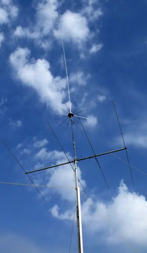
View attachment 9633

Concerning the source. I can make the source for the dipoles split and get closer to the center, but we here discussions all the time about dipoles needing a choke of some kind at the feed point in order to balance the feed point currents, else we are likely to have CMC that ill-affect the pattern and performance. I will post the results if this change makes a noticeable difference.

I did not consider the source of the 5/8 wave models in this case. I just placed them as close to the base as I could. Changing the source will have an effect however.

In reference to the Maxwell article, even ground wires can radiate if they are not kept below 1/4 wl to achieve a very low reactance rf ground. The rf ground, if established, would then be a much easier path, compared to the high impedance that would be encountered back to the ac service through the neutral conductor.

I'm really enjoying the thread. 73, Dave
 
I thought I had explained this before. I tried it with a Maco V-58 set of radials and the impedance dropped significantly. I think you're beginning to see the effects of radiation current with respect to the wavelength of the radiator so it shouldn't be too much of a leap to consider current on a radial well under 1/4 wavelength is going to be lower than if it were resonant at 1/4 wave.

You've probably experimented with the angle or radials as many of us have in various designs from the 1/4 wave ground plane to the Sigma. They change the impedance significantly depending on the angle. Downward slopes match 1/4 waves well while the 90 degree angle assists with the matching of most 1/2 and 5/8 waves.

The makers of the Imax knew they had to sweep the radials down to have the least impact on their original matching network and once they cut them so short of resonance they literally turned them into nothing more than eye candy.

I must have missed the point you were making when you posted about the Maco GPK, or I didn't see it at all.

If the radials, in this case work like you suggest, then your comments about Solarcon makes good sense. I can't remember what-does-what with radials on the Imax, but I do know for sure radials work well to raise and improve the look of the match with a 1/4 wave radiator.
 
SW, may I assume you experimented with the radials on the V58 altering both the lengths, and the angles, and that you did these alterations at different times? And did you combine any of the configurations?

I may not have been specific enough here. I tried using a set of Maco V-58 radials with its 4 pin 90 degree aluminum hub on the Imax 2000. It was many years ago when I lived in a house with a flat roof. I only spent about an hour on it. Simply doing a signal check with no radials and then with the full length set of 4 at 90 degrees. No change in signal could be seen and the impedance dropped to under 40 ohms.

I have also read some of the same materials Marconi refers to about the very small sized radials required to work a 1/2 effectively; other materials, too.

The 1/2 wave is not as dependant on a set of radials as most other end feds are. This is not to say they don't benefit from radials because they do. It just means they will not be as badly effected if you leave them off. I first learned this with my 2 meter hand held. The extended range 1/2 wave telescopic whip always worked better than the 5/8 wave with my arm acting as the counterpoise.

One of the most favored antennas in the EU is the 827, and it does not have 1/4 wave radials. It is very hard to make a case for a decent length set of radials on one of the EU forums because of this.

So now I'd be interested in any details of your findings if they still exist. Perhaps another thread . . . or did you post any of that experiment on the forum already?

The S-827 is a good antenna. At the same time, the Penetrator is a bit better with its longer radials. The differences in gain and CMC are small but worth it to some.
 
Thanks.

I brewed a 5/8 with shortened radials, but found it not to my liking. I felt I could tell it was less a performer than the longer radials models I had made. Much less receive, not hearing at all, nor hearing as well stations I had heard before. The problem with such a comparison for me is that a homebrewer might not make so good an antenna in the first place so the performance difference is owed to the poor construction more so than the potential variables.
The same may be said of any antenna I've made, however, with the amount of time I've spent building, tuning, and adjusting on the majority of them I don't accept that as the case.
That particular antenna went together, accepted the short radials, tuned to low SWR, and flew into the air. I didn't like what I didn't hear, and brought it down.

The point is, I wondered if there was a more detailed test available between us than my own quick trial.

4516.jpg
 
Last edited:
  • Like
Reactions: 1 person

dxChat
Help Users
  • No one is chatting at the moment.