• You can now help support WorldwideDX when you shop on Amazon at no additional cost to you! Simply follow this Shop on Amazon link first and a portion of any purchase is sent to WorldwideDX to help with site costs.
  • The Winners of the three Retevis radios 16 Anniversary giveaway are announced!! Click Here to find out if you won!

DX350 oscillation issue

MKwrench

Wooohoooo!!!
Aug 6, 2023
141
132
53
55
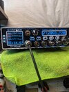
I grabbed a used DX350 and Black Widow DX250 to fiddle around with They both look nice and clean inside and appear to be all original, except for the DX250 having 2879s in it. I rigged up my test equipment as a station monitor switchable between the antenna and test load.
On a dummy load they both look great and show impressive (to me) numbers on my meters.
I adjust the deadkey to 50w for testing the 250 on high where it swings close to 300w PEP.
Then the 350 with a 65w carrier will swing to over 350w PEP.
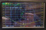
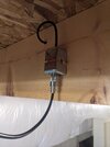
My antenna is an attic dipole with a 1:1 feedpoint choke and great match across the 11m band. When I switch to the antenna vs the dummy load I get a strange oscillation that I found gets better when the carrier is raised on the 350 or the channel frequency is raised on the 250.
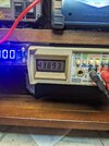
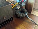
The 1st video is the 350 acting up on the "AM in" setting on the antenna. The 2nd is High on a dummy load. A few more pictures show AMP voltage, Radio voltage and the extra CM choke I rigged up directly behind the amp, and my attic dipole measurments.
I read somewhere that the metalized mica caps can drift causing issues, coud this be whats up here? What do you think?
 

Attachments

  • A.Low DX350.mp4
    280.6 MB
  • D.High DX350.mp4
    90.3 MB
  • Rad.PS.V.jpg
    Rad.PS.V.jpg
    2 MB · Views: 21
  • Amp.PS.V.jpg
    Amp.PS.V.jpg
    1.3 MB · Views: 22
  • 11M.CMC.jpg
    11M.CMC.jpg
    1.8 MB · Views: 22
  • Attic Dipole.jpg
    Attic Dipole.jpg
    904.9 KB · Views: 22

Don't remember seeing the metal-clad mica caps go bad. Does make me suspect either a loose circuit-board screw or missing/ damaged negative-feedback resistor/capacitor issue. I have seen the capacitor on the secondary of the input transformer go bad and create issues. Worth checking.

73
 
  • Like
Reactions: MKwrench
I'm glad you responded, I'm a little more confident about getting in there and checking things out. I'll start with the feedback sets as recommended.
I'm really not familiar with the insides of these yet.
 
Why does that balun look like it is at the radio end instead of at the dipole? The balun needs to be at the antenna's feed point, not at the radio.

Add a common mode choke at the feedpoint, maybe more than the toroid too. Wind some coax coils if you can.

A 1:1 SWR does not mean the parasitic oscillation (different frequency) sees a 1:1 SWR. If improving the common-mode rejection does not improve things, change coax length to hopefully make the antenna system not support the self-oscillation frequency.
 
  • Like
Reactions: MKwrench
The antenna has one at the feed point already, I just added that other one to see if it changed anything. I agree that it's going to be the antenna causing the issue, I'm finding out that the further I go into the 10m band from 11m the better that carrier behaves.
The feed point balun is a mix 43 240 core, dual bifilar wound with 14ga speaker wire 6 wraps per side, the new one I just put together (is behind the radio now) uses Teflon wire instead, I was going to swap it out tomorrow. The radials on the dipole itself are 12 gauge solid core insulated wire from some leftover Romex I had laying around.
 
Last edited:
Okay I think We got it, My feed line is two sections of LSR240 (supposedly equivlent to LMR240), One 50' run from my attic feedpoint balun down to the basement, and anorher 20' or so from that point to the transceivers. Its where I had them connected that caused my problems.

I didn't have a "barrel" connector or a SO end to fit the 240 line, but I did have an old TVI trap to use in place of a "barrel" with two PLs. I thought it was a convenient way to kill 2 birds with one stone and mounted it to the basement rafters (or floor joist... whatever).

Just now, I removed the balun/choke from behind the amp, the little antenna that was fine gets the fuuzzieness now too. Then, I removed the TVI trap in the dipole line and the issue dissapeared.....
Now I see the issue closer to the top of band 5 on the Stryker. I'll deal with that crap another day, It still works nice up there on SSB, so I can still yap in the 28s.

Cool, I'm glad I dont need to repair anything in the amp, I'll work on the aesthetics instead.
But, stay tuned I havn't tried the 250 again yet,....
 

Attachments

  • TVI.jpg
    TVI.jpg
    1.3 MB · Views: 10
On another note: Something I just read says that my parallel wound choke cuts the common mode resistance in half, I thought it was the other way around, while increasing the power handling.
Then asking AI, suggests "twisting" a singular bifilar pair for maximum common mode choking and a better impedance match. I had always thought that twisting was a big mistake and that flat windings are best.
Maybe this is another thread....
 
Now after swapping jumpers and meters around a few times chasing the issue at the other bands, I discover that the jumper between the radio and the amp make a huge change an RG58 3' gives me a wide range without the issue, a 8X 1' gives a little less and a LMR240 3' is terrible with a real thin range. I believe this has to do with the amount of loss in each cable crossing a "padding" threshold that changes reflection.

When I put a meter between the amp and radio.... SWR is insane at the high power level, but completely fine everywhere else. Even on the dummy load, but only on high.
I'm searching for a thread where I thought someone mentions a variable cap to chill the input in the amp. Is anyone familiar with that?

It's an issue I'd like to fix even if it's not the exact issue I'm chasing, but I'm sure it's relative... In the meantime I'll enjoy what I have without running it on high.
 

dxChat
Help Users
  • No one is chatting at the moment.