• You can now help support WorldwideDX when you shop on Amazon at no additional cost to you! Simply follow this Shop on Amazon link first and a portion of any purchase is sent to WorldwideDX to help with site costs.

Fc347 frequency counter... Intall on president McKinley

red97k1500

Well-Known Member
Nov 26, 2012
359
291
73
texas
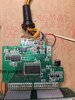
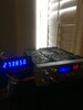
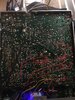
I am by no means a tech, but I was able to wire up a fc347 counter, to my old mb8719 lol president McKinley cb radio. I actually got it to work right! I watched a couple of YouTube videos by mikes radio repair and LesComm.

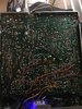
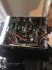
My question is to those of you that have actually installed one of these in a mobile radio.How did you route the wires out of the radio? I have no problem with drilling holes in the radio, but I do want to do this as cleanly as possible.Im thinking of cutting a rectangle hole in the back of the chassis like a factory galaxy radio. If any body has any pictures of how they routed there’s that would be great.
I’m here to learn and open to peoples suggestions, thanks
 

Attachments

  • 4ABA5B62-C617-4717-8B6F-DB9AFC4AD49F.jpeg
    4ABA5B62-C617-4717-8B6F-DB9AFC4AD49F.jpeg
    1.2 MB · Views: 45
  • DC3D1398-8BB9-43C3-A6A5-286C167B0B95.jpeg
    DC3D1398-8BB9-43C3-A6A5-286C167B0B95.jpeg
    1.8 MB · Views: 40
  • 1C62F463-757C-410C-A498-7B8EC3D2EF53.jpeg
    1C62F463-757C-410C-A498-7B8EC3D2EF53.jpeg
    681.9 KB · Views: 42

I have 2 radios with the 347 counter on them. the 148 has a small slot on the case in the back of the radio and the plug sticks out under the cover and no pinch point on this one., I have a Uniden LT that I made a rectangular hole in the back and mounted the plug just like a galaxy or ranger so either way will work. I have a couple of the metal nippers from radio shack that worked just fine to make the hole in the back just drilled a small starter hole the used the nippers to cut it out to size. the nippers make s square bite not round so it was easy to cut it out.
 
Ok I’m going to cut a hole in the back of the radio, probably towards the middle. Is there any thing I should avoid routing the wires next to,That could lead to the radio drifting or cause other problems? I don’t see a good way on this radio to route the wires out, without drilling. One more question, when I transmit on upper or lower sideband the frequency jumps around...I’m guessing that’s normal for these counters? I know on the cheap dosys they can only read right on am, I also have a wireless hand held mfj counter that uses a telescoping antenna that does the same thing. Sometimes if you say auuuuuh steadily into the mic or play a tone, you can get it to display right for one second.
 
I think I’m gonna make a rectangular hole for the plug they supply. I’m gunna drill to pilot holes,then use a dremmel with a tiny cut off wheel. And a mini Swiss file set I have to finish shaping the hole.

What about the counter, is it normal for it to jump around on Ssb transmit?
 
I’m not sure I understand? I do have a radio shack swr/power meter inline between the radio and the antenna. I do not own a bench style frequency counter, like the kind you would use to do alignments. All I own is a mfj wireless style one that has a telescoping antenna, and this fc 347
 
I do not know this radio and there was 2 or 3 versions of it. some were AM FM AND SSB and some just AM, SSB. one thing I would do is make sure the 3 power leads are wired to the proper locations. the 3 leads one will go to AM, one to LSB and the other to USB. they should be hooked up to the board where the main selector wires hook to the board. there should be 4 wires to the AM, SSB switch . one is hot all the time. when in AM mode the wire on the switch for AM is hot and the ssb wires are dead. when put into LSB mode the AM wire is dead and so on. hook each of the 3 347 power wires to the board where the 3 wires go to and see if this correct the ssb jumping problem stops. from looking at the wires on the picture you took of the board they are all over the place. normally the 3 switch wires are close together . verify you have the counter wires hooked up to the proper ssb positions on the main board.
 
  • Like
Reactions: Shadetree Mechanic
I’m not at home right now, so I will have to mess with the radio tomorrow morning... the radio is a single conversion uniden made 40 channel. FCC approved am ssb.... pc 385... supposed to be the same board as a cobra140gtl,142gtl,uniden Washington,tram d300,realistic trc450.... etc
 

Attachments

  • 061728DE-F61F-4AE2-98BC-3BF1D08E0131.jpeg
    061728DE-F61F-4AE2-98BC-3BF1D08E0131.jpeg
    879.1 KB · Views: 31
Small update the display on the fc347 does not jump around in any mode when txing into a 50 ohm dummy load.... but when connected to my a99 antenna it does.
 
Well I messed with it all morning, It still does it on the dummy load but not as bad if that makes since... I removed the variable power, To see if that would make a difference, it did not really help. If I turned the mic gain down low enough, on ssb it would be stable on tx... also if I turn down the am dead key down low it would stabilize on the regular 40....I’m talking like two watts...Talking loudly or whistling makes it jump.On all the upper channels it goes haywire especially above 27.495... I’m not going to be txing above or below the regular 40. But I would still like it to work.... Part of the problem is I don’t really know what I’m doing lol..

I’m posting a picture of what I did to modify the counter to make it work wit my radio... it works awesome on receive and is totally stable.

I had to remove a resistor and make a solder bridge... I soldered a 0 ohm resistor at jp1... I used a 18pf npo 0805 size ceramic capacitor next to the variable capacitor because it was reading low before
 

Attachments

  • F84BF2FE-C0D3-4B4F-AD09-9DB82532C87A.jpeg
    F84BF2FE-C0D3-4B4F-AD09-9DB82532C87A.jpeg
    852.2 KB · Views: 32

dxChat
Help Users
  • No one is chatting at the moment.