
Q37 is the voltage regulator that provides a steady 9 Volts to the transmit/receive switching circuits. If it fluctuates like that, stuff gets twitchy.
I became impatient with fixing this regulator circuit. You pretty much have to take Q35, D72 and D73 each loose to test them. We adopted the policy of using a 7808T TO-220 3-terminal regulator to replace it. We add a 1N4001 diode between the chip's ground (center) pin and circuit-board ground.
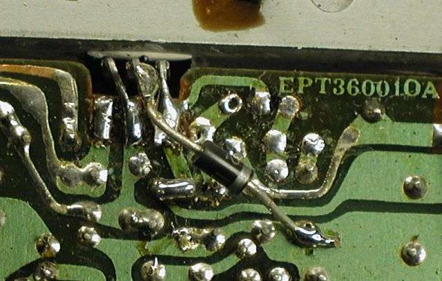
The chip's center pin is in fact connected ONLY to the diode, not to the circuit board directly. The pic doesn't offer a clear perspective view of this.
The diode boosts the output of the 8-Volt chip close to 9 Volts. And if you can find a 7809T that's simpler. No diode required.
This radio probably won't behave itself until it has a steady source of regulated 9 Volts.
73
I became impatient with fixing this regulator circuit. You pretty much have to take Q35, D72 and D73 each loose to test them. We adopted the policy of using a 7808T TO-220 3-terminal regulator to replace it. We add a 1N4001 diode between the chip's ground (center) pin and circuit-board ground.
The chip's center pin is in fact connected ONLY to the diode, not to the circuit board directly. The pic doesn't offer a clear perspective view of this.
The diode boosts the output of the 8-Volt chip close to 9 Volts. And if you can find a 7809T that's simpler. No diode required.
This radio probably won't behave itself until it has a steady source of regulated 9 Volts.
73

