• You can now help support WorldwideDX when you shop on Amazon at no additional cost to you! Simply follow this Shop on Amazon link first and a portion of any purchase is sent to WorldwideDX to help with site costs.
  • The Winners of the three Retevis radios 16 Anniversary giveaway are announced!! Click Here to find out if you won!

Help with Uniden Grant XL

crappykraco

W9WDX Amateur Radio Club Member
Aug 6, 2014
113
51
38
I have a Grant XL purchased on ebay. When I got it it would power up, receive just fine, but no TX light change. I found cracked solder joints on all three legs of the final and repaired. Did a shotgun replacement of all electrolytic caps (it had black YEC for the most part), and got TX back.

Grant XL into a watt meter and dummy load yields the following:

AM mode channel 1: 1/2 watt DK swings to 4 watts
AM mode channel 20: 1/2 watt DK swings to 4+ watts
AM mode channel 40: 1/2 watt DK swings to 3 watts

LSB channel 1: 5 watts
LSB channel 20: 6 watts
LSB channel 40: 3 watts

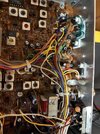
So uneven and lower than expected TX power. I've included a picture. I see one coil is missing its wax and has been adjusted and it looks like a couple wires used to be soldered to the back of audio transformer.

I am an electronics novice at best, but have some basic test equipment and can solder.

I have a multimeter, BK 1040, a freq counter and an old hitachi scope but I'm 95% clueless when it comes to using it.
I hope to be able to return this radio to normal operation with help from the kind folks here.
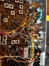
 

Do you have an alignment tool with the proper 1.5 mm tip on it? The old G-C number for that one was 9440. They show up on fleabay. Just don't try to use a metal screwdriver to adjust the small tuning cores. The entire problem may be alignment. The black ferrite cores (slugs) are brittle. If you crack one, that can be a headache.

Do you have a dummy load and source of an audio tone? My preferred way to peak the adjustments in the transmit chain is on SSB with a steady tone into the mike, turned down under a Watt. This makes peak settings easier to observe.

Not much point to digging deeper until you're sure it's aligned for max power.

73
 
  • Like
Reactions: Woody-202
i am using these instructions.. not sure if 100% the same. My radio has PB-208AD

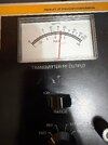
Nomad: Yes i do have an assortment of plastic tuning tools and have one that fits. I have a BK1040 so that is my watt meter, dummy load, and audio source for 1hkz tone.

On CH 19 USB used BK1040 to inject 1khz tone into the microphone. Adjusted L47,L48,L46,L45, L38.
I saw a positive result right away, the smallest adjustment to L47 and the radio pegged the 10 watt scale. Went through the rest and this was the best I was able to achieve.. more like it I think. VR11 seems to work, but feels awful to turn and creaks and groans.


When checking the driver and final bias I am not able to get a reading above 18.5ma.. Unsure if I may be doing something incorrectly. I'm pulling the wire from tp 8 and inserting my black probe into that pulled wire, and putting red probe on the TP, key mic and adjust vr9 looking for 25ma. Similar procedure for the final. I see 18.5ma in both places and no matter what i do to VR8 or VR9 i see no change.
 

Attachments

  • 1040.jpg
    1040.jpg
    1.3 MB · Views: 1
I'm sorry if my questions are silly! I wish I had someone local to sit down with and learn from.
When the alignment procedure says "input of oscilloscope to TP2, adjust for maximum" what exactly does it mean? adjust for maximum what? I don't know what I'm looking for on the scope.

Counter hooked to TP3, I was able to get the USB and AM adjusted to 34.985, and 34.9815. Attempted to adjust L22 for 34.9885 in LSB but couldn't quite get there with the clarifier knob in the middle. i can get to 34.9874 with l22 turned what seems like its max adjustment.
 
Last edited:

dxChat
Help Users
  • No one is chatting at the moment.