• You can now help support WorldwideDX when you shop on Amazon at no additional cost to you! Simply follow this Shop on Amazon link first and a portion of any purchase is sent to WorldwideDX to help with site costs.

Homebrew 572B amp

Captain Kilowatt

Professional Amateur
Staff member
Apr 6, 2005
17,255
12,110
823
60
Nova Scotia,Canada
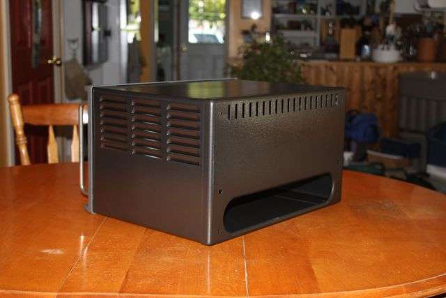
Well I just got off work this morning and thought I would start this thread before catching a nap.As discussed in the other thread,I plan to build a 4 tube 572B amp I have a cabinet that needs some paint and the first decent day I get next week it shall receive that paint.Black hammertone on the outside and a flat textured black on the inside. The front panel will be either hammertone gray or just regular gray.Here is the cabinet.Note the 12 inch ruler for scale.

img1171sm.jpg


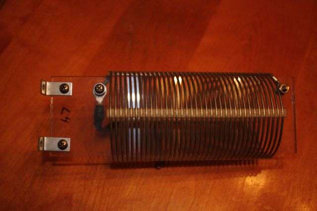
Here is the loading cap I was going to use. It is 2000 pF but is too long and quite hard to modify. It has ceramic insulators holding it together and that makes it pretty hard to shorten. I have some other caps suitable for loading caps in an amp this size so it's time to find out where I stashed all my goodies.

img1175sm.jpg


Updates in a few days after I have a chance to get to it. I work Monday and Tuesday and then off for nine days,back for two more and off another six so I hope to get a decent start on this project.
 

Thats a nice looking cabinet! It should work out fine.
One question. How much room is under the chassis? Or is it flat bottom and up?

Reason I ask is it possible to use that capacitor under the chassis (Legnth ways) and turn it with some sort of manual drive?

This is going to be fun with two homebrew amp threads. :)
 
I forgot to mention that the cabinet is empty,there is no chassis. I will make one from some aluminum panels I have. It will be bolted to the front panel and the entire chassis will be able to be slid out the front leaving the empty cabinet behind. The panel that you see that is gray in colour and has the rack handles is grooved and mates perfectly with the cabinet. It is just sitting there in the picture and is not fixed to the rest of the cabinet. A simple raised chassis and a couple tiedown bolts should do the job. As for under chassis mounting of the cap, I don't have the room ( I don't think) but I will look further into that. I had thought the same thing when I found my right-angle reduction drive seen here.

img1185sm.jpg


The potential new loading capacitor if the big one does not fit. It needs a little cleaning but no big deal.


img1186sm.jpg


The plate tuning capacitor,a Cardwell T-199.

img1187sm.jpg


Possible Pi network inductor. It was the coil for the second harmonic trap in an RCA 1 Kw AM broadcast transmitter.

img1188sm.jpg


One of several ceramic RF switches I have. In this configuration it will serve as both input and output network switches.The single section will select the tap on the final tank coil while the dual section will select the appropriate tuned input for each band.The dual section input section will be housed in a shielded enclosure.

img1190sm.jpg


And last but not least for now, the plate tranny. The primary is either 208 or 240 volts and you can select +/- 11 volts from that. Normaly primary connects to the 0 and 240 terminals. The secondary is either 930 or 1150 volts with Hi/Lo taps for +/- a bit. With the 1150 and Hi taps used the power supply will deliver 2000 volts using a 100 uF filter capacitor rated at 2500 volts.

img1194sm.jpg


This is starting to become fun. (y)
 
And fun it will be.
Any particular schematic you going to work off of?
I been looking at the Dentron Clipperton with the 4 572B's

BTW, I would kill for that transformer. Was going to Maysville hamfest next week to find me one but dont think I am going to be able now.
 
Not following any one particular design really. The basic amp portion is really pretty simply. It's making all the switching and control systems work that is the challange. Things like step-start timing for the plate supply and inrush protection for the filamants and some type of ALC as well as designing the tuned input is what is going to be the head scratching part.

As for the transformer,I hope it will be heavy enough.I have no idea what kind of current it is rated for. It is a Kenyon transformer and finding data on it is next to impossible. It was originally the 4-400 screen supply transformer in the old RCA b'cast TX. I'll have to take a pic of the plate tranny for the BIG amp I want to build later. If you like the one above, all I can say about the other one is :p:. Here's a hint:it weighs 85 pounds. :love:

I hear that.
I been looking at the AL-572 and the Collins: 30L-1 for ideas with mine.

Man that is a heavy duty transformer. I hope it has wheels!
 
Man that is a heavy duty transformer. I hope it has wheels!

No, but the 42 inch high Hammond rack cabinet it will be in does. (y)
You should have seen me carry it up the basement steps and then decide I was going to put that project on hold and then carry it back down the basement steps. :headbang:censored: :eek:
It was the plate transformer for,you guessed, the RCA 1Kw broadcast tx I scrapped after it had a modulator meltdown. It creamed everything from the mod tranny back thru the 4-400 modulator tubes and took out one of two 2E26 audio pre-drivers. :oops: :cry: It powered a pair of 4-400's in class C plate modulated RF service to make 1 Kw carrier (CCS) with 100% modulation that came from another pair of 4-400's in class B modulator service so it should settle in quite nicely as an amateur amp being operated ICAS.(y)
 
No more progress in the last couple days except for looking for and finding some more parts. I need to build a chassis and plan a layout of the components. It's going to be a tight fit but I think it will all come together.I think I will lay it all out on bristle board first and mark holes etc. that way I can simple use it as a template to drill and blast the holes. Looks like a lot of wet weather the next week so I may be able to get something done. I managed to hurt my hand at work the other day and it makes for holding things and fine movements of the right thumb a bit difficult and a lot painfull. I was asked to hold a wrench on a nut that was spinning as another guy tightened the bolt from below the machine.Unknownst to me just as I reached for it another guy in maintenance thought he would be smart and put his air impact driver on the bolt head. :oops: The wrench made a 270º turn in a flash before coming to a stop at the base of my right thumb between the thumb and index finger,bruising a tendon in the process. I don't actually recall having anything hurt so damned bad in my life and that includes the time I crushed a finger in between two rollers. :censored: The swelling has caused my thumb to want to lock up a bit when bending it at the middle joint and it really hurts. Hopefully in another couple days it won't be as bad and I can actually do some things I want to since I just started a break from work of nine days off. I go back for just two days and then I am off for another six days so I had better be able to take advantage of the down time to work on this project. It happens to be my right hand too and I am right handed as well. It figures.Anyway in the meantime I am still gathering bits and pieces and the more I find the better I feel about it. I think I have everything now except the actual tubes and a filamant transformer.I was sure I had a xmfr but cannot seem to locate it.I do have a xmfr that I may try my hand at rewinding the secondary of to get whet I need. I have done that a couple times in the past but if my hand takes too long to feel better I just may say WTF and buy one.
 
Hate to hear about your hand incident. Hope it heals soon.
Pain stops everything!

Sort of at a stand still on mine also at the moment. Its gathering time. I will update that thread shorly.

Your template idea sounds like the way to go. Noo need to drill holes only to find it should had been another way. I have wind a few transformers also but you need three hands to do it right;)

Take care and rest that hand!
 
Not much of an update but not much has been done lately. I have been tearing the shack apart in preparation of a complete rebuild from the ceiling to the floor so the amp project has been put aside for a short bit. If you remember, the cabinet I was going to use was in dire need of a little TLC and some paint.Well here it is after getting what it needed. The cabinet is painted "textured" black on the inside and Hammertone black on the outside. The front panel is hammertone gray and the escutcheon/bezel around the front panel is painted with a textured grey. The textured paint is not quite flat but not quite gloss finish,more like a satin finish, and feels slightly rough to the touch.It gives what I think is a nice grainy look. I think the colour scheme worked out well.


img1200sm.jpg


img1201sm.jpg
 
Well I have had it. I'm tired of trying to fit 10 lbs. of shit into a 9 lb. bag. Yeah I know the saying is a 5 pound bag but in this case 9 pounds more closely reflects just how close I am to getting things to fit. In fact I can get everything to fit but some things are too close or oriented the wrong way ie. the tank coil should be parallel to the tune/load caps to minimize coupling but I can't do that. The solution is to build a separate RF deck and power supply. The RF deck will go into the cabinet pictured above quite nicely without any power supply components hogging the room. This gives me some room for options. I have a couple old steel chassis that held some VHF airband tube gear that once belonged to the Canadian airforce.They look pretty buzzardly but that just adds to the charm. :D I picked them up about 20 years ago and thankfully never got rid of them. They also contain a pair of plate transformers and a pair of filament transformers as well as power supply chokes etc. Everything is Hammond and built to RCAF military spec,in other words under rated. The pair of plate xmfr's in series so I can run on 240 volts will give me a DC output of 1800 volts no load at .75 amps continously.The filament xmfr's are rated at 10 amps each so I can parallel them and get all the amps I need and then some for the 572B's. On the other hand I have a plate xmfr from an old Collins 500 watt (?) broadcast TX and it's companion choke.The problem is that the volts may be a bit too high for the 572B's with this setup. It is 6400 volts output centre tapped to ground. This means 3200 volts into a full wave rectifier (not a bridge) and then into the choke.Total DC output may be in the order of 2800-3000 volts which is too high for the 572B's. Looks like its time to set things up and do some voltage tests. Typing that last line reminded me of the last time I messed around with that xmfr.The details are in the following thread.

http://www.worldwidedx.com/general-ham-radio-discussion/30597-watch-those-meter-leads.html


This time do have the proper leads. Hopefully in the next day or two I will test the xmfr's and decide which ones to use and in what config. Separating the RF deck and power supply leaves me with a lot more options. Pictures to follow after more voltage tests are done.
 
I forgot to mention that the cabinet is empty,there is no chassis. I will make one from some aluminum panels I have. It will be bolted to the front panel and the entire chassis will be able to be slid out the front leaving the empty cabinet behind. The panel that you see that is gray in colour and has the rack handles is grooved and mates perfectly with the cabinet. It is just sitting there in the picture and is not fixed to the rest of the cabinet. A simple raised chassis and a couple tiedown bolts should do the job. As for under chassis mounting of the cap, I don't have the room ( I don't think) but I will look further into that. I had thought the same thing when I found my right-angle reduction drive seen here.

img1185sm.jpg


The potential new loading capacitor if the big one does not fit. It needs a little cleaning but no big deal.


img1186sm.jpg


The plate tuning capacitor,a Cardwell T-199.

img1187sm.jpg


Possible Pi network inductor. It was the coil for the second harmonic trap in an RCA 1 Kw AM broadcast transmitter.

img1188sm.jpg


One of several ceramic RF switches I have. In this configuration it will serve as both input and output network switches.The single section will select the tap on the final tank coil while the dual section will select the appropriate tuned input for each band.The dual section input section will be housed in a shielded enclosure.

img1190sm.jpg


And last but not least for now, the plate tranny. The primary is either 208 or 240 volts and you can select +/- 11 volts from that. Normaly primary connects to the 0 and 240 terminals. The secondary is either 930 or 1150 volts with Hi/Lo taps for +/- a bit. With the 1150 and Hi taps used the power supply will deliver 2000 volts using a 100 uF filter capacitor rated at 2500 volts.

img1194sm.jpg


This is starting to become fun. (y)
1150 x 1.41 equals 1621.5 with a full wave bridge not 2000 volts
 
1150 x 1.41 equals 1621.5 with a full wave bridge not 2000 volts


Yes, I am aware that the DC output is equal to the applied AC voltage times the square root of 2. That was one of the first things I learned during my electronics training which lead me to become a commercial broadcast engineer for 22 years :D. I believe you missed the part where I said it has taps for "HI" and "LO". See included picture attached to that post. Selecting the 1150 AND the "HI" tap yields about 1400 volts AC output. Trust me. I wired it up on the kitchen table and tested the voltage, or as we say in the business about anything that high, the joltage. ;)
 
Not much of an update this time. Lots of things to do before winter sets in. The last update saw me decide to build a separate power supply and RF deck. Here is the old chassis I plan to use for the power supply. I forgot to take a picture of it before I cut out the old steel deck. It had about a dozen holes in it from where rectifier tubes and transformers/chokes/capacitors etc. were mounted. It was an old power supply chassis from some air force air band equipment. Although it was air band it was ground based and was 60 Hz stuff. At least I can use the filament transformers that were in it. Here is the chassis after cutting out the old deck panel and prior to installing thge new one.


img1202sm.jpg


Here is the front panel. Note lots of holes for fuses along the bottom. The two elongated holes are fro breakers that I may be able to use as well. The two large round holes near the top are large pilot lamps,one red the other green. I figure the red will be filaments and the green for the plates. that way with the filaments on but no plate voltage the supply will indicate a ready but standby no-go status with the red light.


img1203sm.jpg


It also has rack mount handles for the front. It has had a coat of paint and hopefully tomorrow I can post a picture of it with the front panel components installed. It will have an enclosure built to cover the beast and the whole thing will possibly be on wheels if I floor mount it. Hopefully if the paint dries overnight I can layout the components for the power supply and get some voltage measurements made so I can determine just what configuration I will use.
 

dxChat
Help Users
  • No one is chatting at the moment.
  • @ Wildcat27:
    Hello I have a old school 2950 receives great on all modes and transmits great on AM but no transmit on SSB. Does anyone have any idea?
  • @ ButtFuzz:
    Good evening from Sunny Salem! What’s shaking?
  • dxBot:
    63Sprint has left the room.
  • dxBot:
    kennyjames 0151 has left the room.