B

You are using an out of date browser. It may not display this or other websites correctly.
You should upgrade or use an alternative browser.
You should upgrade or use an alternative browser.
-
You can now help support WorldwideDX when you shop on Amazon at no additional cost to you! Simply follow this Shop on Amazon link first and a portion of any purchase is sent to WorldwideDX to help with site costs.
-
A Winner has been chosen for the 2026 July 4th Retevis RA89R Giveaway! Click Here to see who won!
Homemade Sigma 4 11 meter base antenna
- Thread starter Lil'Yeshua
- Start date
If the currents inside the 'cone' are equal and opposite of those outside the 'cone', what determines it's phase so that they 'cancel'?
- 'Doc
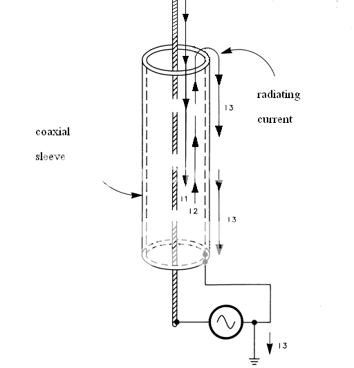
The currents inside the cone are equal and opposite, the antenna mast and the current on the inside of the basket are contained within the basket, similar to coax in a balanced mode, however the additional current on the outside of the basket is similar to common mode current on coax, however in the case of the Sigma 4 it is additional and radiates in phase with the main element, this counteracts the normal drawback with a 3/4WL antenna where the lower lobe would be out of phase, causing a higher angle of radiation.
Hope that makes sense
")
It would be insteresting to construct a coax cable version of the Sigma 4, I'll have to get my thinking hat on as to how it could be deployed and the impedance mismatch accounted for, velocity factor may be an issue though (just thinking out aloud) :blink:
The reason a coax cable works is due to the opposing currents carried along the outer of the centre conductor and the inside of the outer screen, any current on the outside of the screen, CMC, will radiate, this is why coax can sometimes be called unbalanced.
Twin feeder cable carries opposing currents and without the outer screen of a coax doesn't carry CMC, and is typically called a balanced feed, a bit like a J Pole.
If I understand correctly, the cone behaves like coaxial cable, with opposing current contained within the basket and in phase common mode current on the outside of the basket.
Maybe
35, I agree with you, but the magnitude of the CMC seems to me to vary with the difference in magnitude of the two out of phase parallel currents...at the load end of the coax. I don't think we will ever see a perfect CMC free setup, so we can only hope the current is small enough not to cause problems or skew the pattern too much.
IMO, the main reason we see CMC that present problems in real world installs is due to the lack of coaxial balance at the feed point, and the lack of balance in the vertical antenna designs we use. Of course the problem depends on the magnitude of CMC, so a little is not always bad.
In real installs it is difficult to determine exactly how far away from the feed point we find the actual ground termination. Thus the overall coaxial feed line that originates at our transmitter may be 50' feet long physically, but the shield side is likely way longer...considering the actual ground termination may be in your neighbor's back yard. See Maxwell below at 21-3, at my notation "Ground (shield) is also important" to consider...and seldom is.
View attachment Maxwell 21-3.pdf
On the other hand, when we use an analyzer or model antennas, the feed line length is typically shows to be well balanced by the device used. Modeling sets the ground at Earth where you set the mast so the shield and the center conductor are alway equal in length if we use a feed line between the feed point and Earth. Thus we are likely to see differences in results. How much difference does this make, I don't know, but it is a difference that is seldom consider when we discuss CMC's, the lack of balance, and asymmetry in our antenna designs.
I know if has been said that Eznec will not show the proper currents for the Vector, but I have a model of the Vector at 36' feet that indicates the current in the bottom segment, the base of the 4 radials shows to be +.28701 amps. If these 4 radial currents are summed, they equal +1.14804 amps, while the bottom segment of the radiator shows to be -1.1364 amps or +0.01164 difference...thus it could be said there are minimal CMC indicated in this model.
I've suggested this before, but I see very strong currents flowing in the bottom of my Vector model, but these currents, being virtually parallel, are showing near equal magnitudes and are out of phase, so I see mostly cancellation occurring.
I also see the animated image of the CST model, and that too looks like there is RF being generated by the cone, but I'm not quite convinced yet. Plus we have very scant details of what we are actually looking at with this CST image...except maybe for Bob's new image with some new arrows which don't exactly compared to his previous EzBob model.
Hey Bob, did you get a new EzBob version update from CST?

I think some of the modelling shortfalls with Eznec may be as a result of the NEC 2 engine, the later professional version of Eznec is NEC4 based, however unless you're a wealthy man it's a bit expensive as you need both a NEC4 licence and the Eznec licence.
I came across this issue when attempting to model an inverted L with one 20' radial that L.B Cebik had suggested in an artical, Cebik had a number of plots for different frequencies and I couldn't get my model to display anywhere near the same plots, however it took 16 radials to reproduce his results, this was a shortfall in the software based on NEC2 of miniNEC3, Cebik was using the NEC4 engine
I came across this issue when attempting to model an inverted L with one 20' radial that L.B Cebik had suggested in an artical, Cebik had a number of plots for different frequencies and I couldn't get my model to display anywhere near the same plots, however it took 16 radials to reproduce his results, this was a shortfall in the software based on NEC2 of miniNEC3, Cebik was using the NEC4 engine
The currents inside the cone are equal and opposite, the antenna mast and the current on the inside of the basket are contained within the basket, similar to coax in a balanced mode, however the additional current on the outside of the basket is similar to common mode current on coax, however in the case of the Sigma 4 it is additional and radiates in phase with the main element, this counteracts the normal drawback with a 3/4WL antenna where the lower lobe would be out of phase, causing a higher angle of radiation.
Hope that makes sense
It would be insteresting to construct a coax cable version of the Sigma 4, I'll have to get my thinking hat on as to how it could be deployed and the impedance mismatch accounted for, velocity factor may be an issue though (just thinking out aloud) :blink:
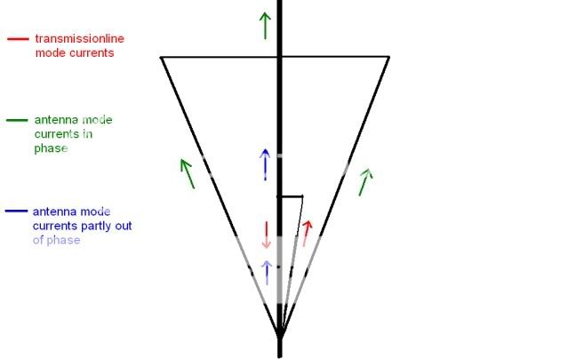
35, this may be a similar question to what 'Doc asked, but I'm not sure. If we have balanced currents between parallel elements that are out of phase (non-radiating feed line theory) as you describe, we have cancellation, unless theory is wrong. I know that Bob has said that this cancellation theory is sometimes wrong, but I don't understand how that can be, and I don't remember what or if he commented on why.
Where do the additional currents on the outside of the basket come from? You describe above in your claim that CMC's are radiating in phase with the radiator. I don't hold to the idea that CMC's can be totally eliminated no more than I believe that we can attain zero at a minimum voltage point, but if these currents, you describe, are large enough to make appreciable RF then the currents inside the cone are no-where near being out of phase.
Do you believe that appreciable CMC's can manifest from the top of the radial hoop on the Vector...a voltage node? If this is so, what is the point of our use of coaxial chokes at a current maximum?
If you'll note, Bob had to change the direction of the current flow on the top 1/2 wave radiator portion of his new image in order to make his idea work out. I can't say that makes this example of what is going on wrong, but it is conveniently different from his previous EzBob model and that is not explained here.
Last edited:
I think some of the modelling shortfalls with Eznec may be as a result of the NEC 2 engine, the later professional version of Eznec is NEC4 based, however unless you're a wealthy man it's a bit expensive as you need both a NEC4 licence and the Eznec licence.
I came across this issue when attempting to model an inverted L with one 20' radial that L.B Cebik had suggested in an artical, Cebik had a number of plots for different frequencies and I couldn't get my model to display anywhere near the same plots, however it took 16 radials to reproduce his results, this was a shortfall in the software based on NEC2 of miniNEC3, Cebik was using the NEC4 engine
I know nothing about the different software engines you note, so there could be a notable difference, but I doubt the difference is as much as you suggest. Do you have specific information that talks about this subject?
I have done something similar in an article where Cebik produced enough modeling details to try and duplicate his work. I only had to figure out close to the height he used and the number of segments...and I got so close I was amazed. I don't know which Eznec he used however.
Could you post a link to that Cebik article you used?
The cone is almost like a focusing lens affecting the overall radiation pattern.
Hey Lil'Yeshua, did you model to get this idea, or are you using a crystal ball?
Hey Lil'Yeshua, did you model to get this idea, or are you using a crystal ball?
To be truthful about it,I am ignorant about it but am curious as to understand how it works. Plus I'm thinking about that being my next antenna.
35, this may be a similar question to what 'Doc asked, but I'm not sure. If we have balanced currents between parallel elements that are out of phase -------
----
Do you believe that appreciable CMC's can manifest from the top of the radial hoop on the Vector...a voltage node? If this is so, what is the point of our use of coaxial chokes at a maxium current node?
If you'll note, Bob had to change the direction of the current flow on the top 1/2 wave radiator portion of his new image in order to make his idea work out. I can't say that makes this example of what is going on wrong, but it is conveniently different from his previous EzBob model and that is not explained here.
A couple of posts further up I again questioned the science behind the Sigma 4 success, not knowing what made it such a high performance antenna, looking at the CST graphic I postulated that the outsied of the basket is in fact radiating and the inside of the basket contains opposing currents, this was based solely on an assessment of the CST graphic, not from any research or personal investigation, I even suggested in the eariler post that I might need to investigate the why and where for of the Sigma 4 to fully understand it's various currents and nodes, this I still have to do.
I'm currently at work and not all graphics will display due to the company security policy, so I'll defer answering all your questions until I'm at home, that said, I agree it is unlikely to see high levels of current at a voltage node, if the hoop is such then I'd expect the maximum current to be at the base of the hoop, in common with normal convention, antennas having a current maximum at a 1/4WL from the tip, the top of the basket being the tip in this case.
Thanks, and I tend to agree with you here.
I may voice an opinion, but I'm not so closed minded as to discredit another view when a good argument is provided.
I look forward to try and confirm your findings using Eznec. If I find the same thing as you did, and don't see a work around, then I'll have to consider to go to another program.
dxChat
- No one is chatting at the moment.