• You can now help support WorldwideDX when you shop on Amazon at no additional cost to you! Simply follow this Shop on Amazon link first and a portion of any purchase is sent to WorldwideDX to help with site costs.

Homemade Sigma 4 11 meter base antenna

seems like i recall some comments about the J-pole being slightly directional because of the 1/4 wave tuning stub ..... am i remembering correctly ? or have i been having too much fun ?? :)
 
There doesn't appear to be a significant amount of difference between the three. As for pattern distortion, that doesn't amount to anything either. Unless an antenna is placed really in the clear of everything around it there will always be some pattern distortion.
You could always put a rotor under that 'J'-pole I guess...
- 'Doc
 
I know a few of the chaps on here have a fair bit of experience with the Sigma 4, Vector variants, and home brew works of art, and I'm prepared to take your various experiences of working with the antenna as proof of the pudding, but I would like to know the essence of what makes this antenna so much more than a J Pole, maybe I'll have to put some effort in for myself, I can see why it probably doesn't suffer the slightly skewed pattern of the J Pole, and as for the feed, well the J Pole isn't fed at its base, but at the 50 ohm point between the two elements, the Sigma using a gamma match.

I can see a Summer project in the making here, but I'll probably buy a second hand antenna rather than scour metal supplies for its components ;)
 
generally it won't, unless if you happen to have someone way up north that you can hit with a jpole, but then you change to the coaxial jpole and then they suddenly can't hear you very well or at all, then all of a sudden one antenna is better than the other;)

if this is the case then you may need that rotor doc is talking about.
 
My testing consistently shows improved coverage with the main radiator tuned to .82 wavelength

Curious about that; Do you mean to say that literally or do you mean to say that you have modeled it?

Both areas Radioman. The CST model I shared showed the antenna as a 3/4 or .75 wave antenna. This is where the model peaks its gain on the horizon and the point where all radiation currents are just about perfectly in phase. The antenna now functions similar to a 1/2 wave over the 1/4 wave cone.

The other variant was the 7/8 wave version that functions more like a 5/8 wave over a 1/4 wave. That model shows out of phase currents produced on the vertical just above the cone. In the field, tests show that a balance between these two provides the best gain on the horizon. That works out to be around .82 wavelength.
 
I would like to know the essence of what makes this antenna so much more than a J Pole.
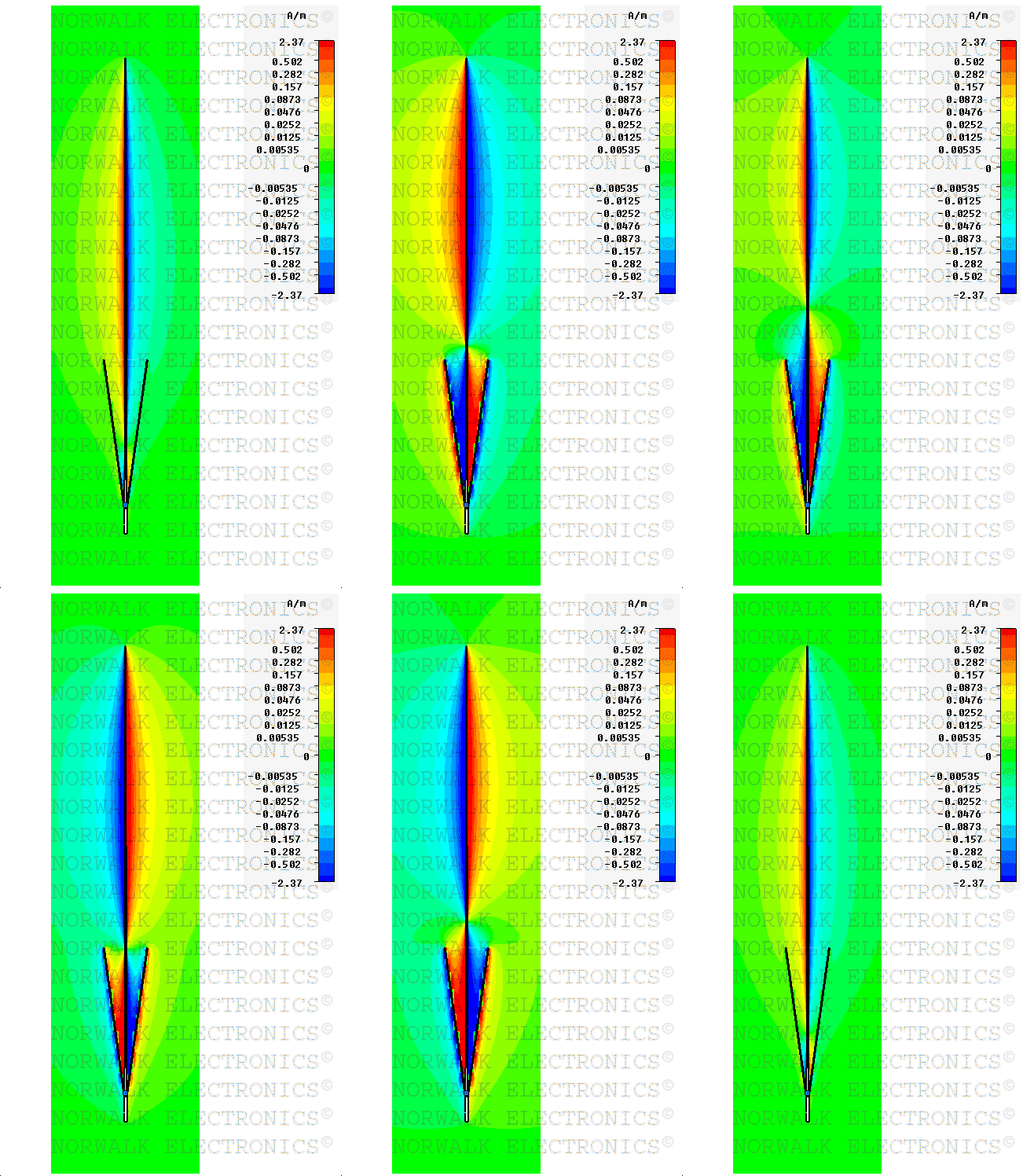
The Sigma design is the first vertical omni I've ever seen that produces two in phase current nodes along the radiator without using an insulator, phasing coil or delay line. The easiest way to visualize this is to look at the CST model posted elsewhere in this forum.
 
Dominator_NWE-34_CST_S.jpg
 
FMBroadcastAntenna.com | FM Broadcast Antenna's

Dominator%20NWE-34%20in%20CST.gif


" ....... Advancements in computer antenna modeling software have made it easier to understand how the Dominator NWE-34 produces more gain then any single other commercially manufactured FM broadcast antenna. CST Microwave Studio is an exceptionally accurate software tool that provides 3D Electro-Magnetic simulation of antennas. The image displays both the magnitude and phase of all radiation currents along the antenna at a driven phase angle that produces maximum current. Clicking on the image above will open a GIF video that shows the currents at all driven phase angles throughout the 360 degree RF sinewave.

Magnitude is displayed with color intensity and referenced to the chart on the right. This chart shows the magnitude in amps per meter for the corresponding colors. Phase is also indicated by opposing colors at the positive top and negative bottom of the chart. The Dominator has obvious characteristics not typically found in antennas other then collinear types. It has 3 separate radiation currents with two allowed to radiate freely in a phase that is constructively combined in the far field. The third current is in a deconstructive phase with respect to the other two and has been confined within the tapered coaxial skeleton cone.

It is the tapered 1/4 wave coaxial cone that sets this antenna apart from others. It allows the longer top section of the main radiator to radiate freely while the deconstructively phased radiation on the lower 1/4 wave of the main radiator is confined within the cone. Since the base of the cone and the base of the main radiator are excited by opposite phase polarities, the currents allowed to radiate on the outside of the shielding cone combine constructively with the longer main radiator extending above the cone. Total currents radiated by the cone are divided into its four vertically tapered radials. This provides noticeable gain over a dipole on the distant horizon. ...... "


a key point rickey ..........

" ........ It is the tapered 1/4 wave coaxial cone that sets this antenna apart from others. It allows the longer top section of the main radiator to radiate freely while the deconstructively phased radiation on the lower 1/4 wave of the main radiator is confined within the cone. ........ "
 
The reason a coax cable works is due to the opposing currents carried along the outer of the centre conductor and the inside of the outer screen, any current on the outside of the screen, CMC, will radiate, this is why coax can sometimes be called unbalanced.

Twin feeder cable carries opposing currents and without the outer screen of a coax doesn't carry CMC, and is typically called a balanced feed, a bit like a J Pole.

If I understand correctly, the cone behaves like coaxial cable, with opposing current contained within the basket and in phase common mode current on the outside of the basket.

Maybe :confused:
 
  • Like
Reactions: 1 person

dxChat
Help Users
  • No one is chatting at the moment.