
You are using an out of date browser. It may not display this or other websites correctly.
You should upgrade or use an alternative browser.
You should upgrade or use an alternative browser.
-
You can now help support WorldwideDX when you shop on Amazon at no additional cost to you! Simply follow this Shop on Amazon link first and a portion of any purchase is sent to WorldwideDX to help with site costs.
-
A Winner has been chosen for the 2026 July 4th Retevis RA89R Giveaway! Click Here to see who won!
I finally ordered the new tower today.
- Thread starter Captain Kilowatt
- Start date
Spent the last day off not doing too much. I had hoped to get the 2m and 6m yagis down off the old tower as the weather was great for it and was thinking my leg was going to allow it but I was wrong. Yesterday, in the middle of the afternoon no less, I watched a bat fly into the attic vent on the end of the house. The wife was with me and was concerned about it being in the attic so I pulled the ladder out and climbed up to the vent to take a look......all two stories and then some to the very peak. Have I mentioned yet that while I have no problem climbing towers I despise and have a fear of tall ladders? Pretty hard to anchor a safety harness to something that can fall with you. Anyway I checked the bat out and he was just in the vent and the screen between him and the attic was intact. He was happily hanging upside down and settled in. I named him Bruce considering that Bruce Wayne's secret identity is Batman. After coming back down the ladder I realized that the muscle in my leg is still not healed enough yet so more wasted time goes by. I turned my attention to finishing the first stage of the tower grounding and bonded the last two tower legs to their respective ground rods and bonded the rods together.
I changed out the original ground rod connectors for something a bit more robust and suitable for being buried. I forgot to take a picture but they are basically an oval made of bronze with a bolt in one end. this allows it to be slipped over a ground rod and a heavy ground wire and tightened up very securely. I used the first type of ground clamps to provide a bit more security to the connection as well as provide a point for the connection that bonds the ground rods together. You can see both types on the rod here.
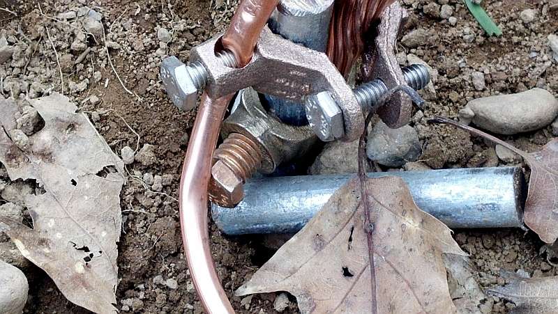
The ground rod bonding material is simply 1/4 inch copper tubing that fits the ground screw nicely. 1/4 inch tubing is roughly equivalent to number 2 gauge wire and has the advantage of greater surface area because of the inside and outside surfaces. Here is the finished product. One ground rod is the full six feet in which includes 4 feet into the shale bed. The others are only five feet deep but at least they are all into the slate bed which is quite wet at that depth. Water was constantly draining INTO the hole that was dug for the tower so I feel that the first stage of lightning protection is adequate. There will be three more rods along the length of the bonding cable running from the tower to the house.
I am also placing an order in the next day or so for three ICE coaxial lightning surge arrestors and a 16 terminal control line arrestor to protect the 6 wires for my rotator as well as the four wires for my antenna switch.


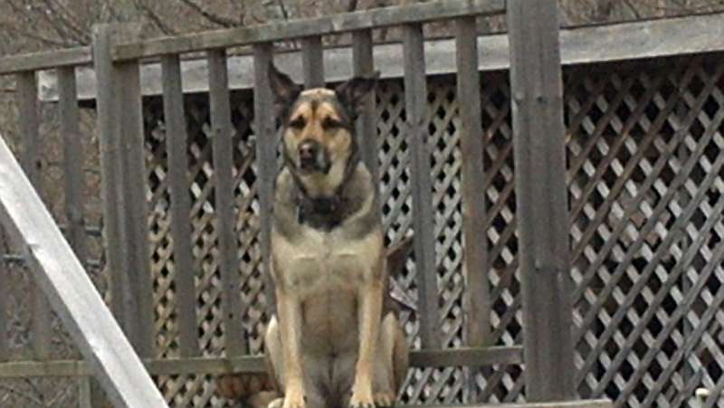
All the while I was working I was under the watchfull eye of my master Sable.
I changed out the original ground rod connectors for something a bit more robust and suitable for being buried. I forgot to take a picture but they are basically an oval made of bronze with a bolt in one end. this allows it to be slipped over a ground rod and a heavy ground wire and tightened up very securely. I used the first type of ground clamps to provide a bit more security to the connection as well as provide a point for the connection that bonds the ground rods together. You can see both types on the rod here.
The ground rod bonding material is simply 1/4 inch copper tubing that fits the ground screw nicely. 1/4 inch tubing is roughly equivalent to number 2 gauge wire and has the advantage of greater surface area because of the inside and outside surfaces. Here is the finished product. One ground rod is the full six feet in which includes 4 feet into the shale bed. The others are only five feet deep but at least they are all into the slate bed which is quite wet at that depth. Water was constantly draining INTO the hole that was dug for the tower so I feel that the first stage of lightning protection is adequate. There will be three more rods along the length of the bonding cable running from the tower to the house.
I am also placing an order in the next day or so for three ICE coaxial lightning surge arrestors and a 16 terminal control line arrestor to protect the 6 wires for my rotator as well as the four wires for my antenna switch.
All the while I was working I was under the watchfull eye of my master Sable.
In reassessing my 2m antenna situation I decided to upgrade from a single Cushcraft A147-11 that I had flipped over to horizontal. While that antenna is a good performer on the FM portion of the band the elements are just not quite long enough to tune well on the bottom end of the band. I decided it was time to flip it back to vertical and look for something else for 2m SSB. I decided on a pair of 13B2's from Cushcraft. They are good performers and have a manageable boom length of 15 feet. They arrived the other day and I spent the last couple days assembling them and making a stacking boom. Ideally they would be one above the other but due to lack of space on my mast it just won't happen and they will ba horizontally polarized and mounted side by side. The mast will already extend 17 feet above the top of the tower and any more is asking for trouble. The antennas are assembled and temporarily mounted at the bottom of the tower to facilitate tuning etc. I made stacking boom from a reinforced Cushcraft A3 tribander boom. I had given thought to the phasing lines and thought I would go the usual route of an odd number of 1/4 wave lengths of 75 ohm cable from the coaxial Tee connector to each antenna. The only thing I do not like with that is that on VHF the lengths become many multiples of a quarter wave and any error in calculations is multiplied. Of course I could always use the MFJ-269 to make sure but I have always wondered about power dividers. A power divider is basically a piece of concentric pipes and connectors that form a rigid coaxial transmission line with the proper impedance to convert from 50 ohms from the transmitter to the nominal 25 ohms that two antennas in parallel present. I found a site with good info on building power dividers and decided to give it a shot.Stacking info using coaxial cable or power dividers (splitters) can be found in the following link.There is a good little program downloadable there that will allow you to design a proper power divider.
stacking with power splitters
To transform 25 ohms to 50 ohms you need a 1/4 wave length of 37.5 ohms transmission line. The sizes worked to to require a square piece of tubing approximately 1 1/4 inches outside measure along with a piece of pipe approximately 0.6 inches. Coincidentally enough I had a pair of 4 foot long booms from old Lindsay VHF antennas that measured slightly over an inch and standard 1/2 inch copper pipe is a little over half an inch OD. I carefully measured the lengths and drilled the square tubing for three type N connectors, one input at one end and two antenna ports at the other, soldered it all up and then tested it. I attached two 50 ohm dummy loads to the antenna ports to simulate the antennas and checked the impedance at the transmitter port with the MFJ-269. The impedance was 50 ohms with 1 ohm of reactance. Not bad for my first attempt at making a power divider I would say! No pictures I am afraid to say. The camera battery was dead but if you look at the link above you will see what I made. What I made looks almost identical. As for power handling, I do not have to worry. The type N connectors will fail long before the 1/2 inch copper pipe feedline.
Well a major step in the ongoing saga was completed today. The old tower and antennas was successfully removed today with the help of my friend Dave. Dave is not into radio but is an IT guy and does have to climb a bit to install wireless internet antennas and is a former military firefighter and climbs confidently. I wasn't sure I was going to be able to climb as I am still having issues with a torn leg muscle which the doctor has told me may take 6 months to completely heal. It has already been three months and it can be agonizing at times when I do certain things. I vowed i would get the antenna down myself as I know how they are mounted and how to overcome all the little problems that would assuredly arise. In short it was a good thing I was able to climb today because of a lot of issues that did come up due to 20 years of being attacked by Mother Nature and my experience in dealing with multiple antenna stacks, rotators, thrust bearings etc. There were several head scratches and work-arounds in getting the old 2m and 6m antennas down. The leg is letting me know that I probably should not have climbed today (as was the wife) but I have until Tuesday before I go back to work.I worked on the tower for over two hours without a break in order to remove them. After break Dave climbed and started to dissassemble the tower.Two hours or a little longer later and we had everything down and all cables pulled from the house.It sure looks funny now in the back yard not seeing the old tower that has stood there for 20 years. With this job completed I am now able to repair the Cushcraft A147-11 which has a single broken element and get it ready for mounting at the very top of the new tower. It will be mounted vertically. The pair of 13B2's are all ready to be mounted at the top as well and will be horizontal for some 2m SSB activity. I just need to make up the phasing harness for it. The home made power divider is all complete and checks out as perfect. Two 50 ohm dummy loads connected to simulate the two antennas read as 50 ohms + J1 on the end going to the shack. Not bad for my first ever power divider project. The 6m antenna looks fine and just needs to have a quick check over and have the connectors on the feedpoint and the 1/2 wave coaxial balun lines resealed against the weather and a new feedline made up to go to the antenna switch and then it too can go up on the new tower. The last antennas to go up are the A3WS for 12m/17m and the Explorer-14 for 10/15/20/40m. It now looks like I may actually have some antennas on the new tower soon!
looking foward to seeing the end result!im sure it will be impressive.Just picked up a new toy myself yesterday.Its a used hygain 54 ft hd tilt / crankup.got it for what i thought was a great price.its going to start looking like an antenna farm around here as i have a 37 foot crankup up already.reading your posts has got me fired up ,thinkin of a 17 meter monoband that i have all the parts for up on it!and im sure some other things hanging off it.
Well the antennas are still not up but things are getting closer. There have just been too many other things to get done now that good weather is upon us. Today and yesterday was spent rebuilding stuff. The Cushcraft A147-11 got a new element to replace the broken #3 director and the gamma match was taken apart and wire brushed to remove the corrosion that had built up on the connections. This was put back together using an anti-oxident paste to prevent it from happening again. The gamma match was also retuned as it had been set for the lower part of the band but only with moderate success as the elements are a bit too short for the SSB portion.I was goinfg to foregoe any 2m FM antennas as I do not really care for repeater work but eventually decided to reinstall it set up as it should be for the FM portion of the band. The SWR was a decent 1.2:1 on 146.800MHz with the antenna standing on it's reflector on the ground. I am sure it will be better once on the tower. A new boom-mast bracket was also made to fit the larger mast
The next antenna is the sideways stacked pair of 13B2's for 2m SSB and the homemade power divider. Heliax was cut and run from each 13B2 to the power divider and sealed. SWR at the input to the power divider was measured as 1.1:1 at 144.250MHz It is now ready to go on the tower.
The 6m yagi was a bit of a puzzle. It worked great and had a great SWR originally but just prior to being taken out of service the SWR was bad. It is fed with a hair pin or Beta match and a 1/2 wave coaxial balun. When I built the antenna I made a bracket with three SO-239 jacks on it, two for the coax balun and one for the feedline. These had a very small amount of corrosion but nothing that should have accounted for the high SWR. When I checked the coaxial balun it just would not check out right and I got different readings on the MFJ-269 analyzer depending on which end was connected to the meter. Strange to say the least. I haven't stripped the cable yet to see if my hunch was correct but it appears that because the cable was foam cored Belden 8214 and was wound in a tight coil about 4 or 5 inches in diameter that the core has migrated in the heat and has developed a short inside the cable about 1/4 the way from one end.A new 1/2 wave balun was made up and installed and the antenna checks out with a 1.1:1 at 50.175MHz. New brackets were made for it as well to fit the larger mast on the new tower.
Next I tackled the Cushcraft A3WS 12/17m duobander which I had partially assembled some months ago.I drilled the mounting plate, again to fit the larger U-bolts for the larger mast, and assembled the elements. About four feet off the ground both 12m and 17m dipped nicely down to 1.1 or 1.2:1 across each band.
Just one more antenna to put together and that is the Hy-Gain Explorer-14 with the QK-710 add on kit to cover 10,15,20, and 40m. The elements are partially assembled now but I need to do something about the element/boom mounting brackets and hardware. I was not pleased with the hardware as it was 1/4-20 stainless which is fine however it was cheap and either broke or seized easily. Also the bolts were a bit too short and the nuts would fall off during assembly while following MFJ's instructions on assembly. The hardware needs to be at least 1/4 inch longer in my opinion and of better grade. I have a bunch of 1/4-20 stainless hardware I may simply use instead or I may drill out all the holes and upgrade to 5/16-18 hardware of which I have tons of. That is the likely option. I also used a spray on anti seize compound super rich in nickel to help prevent seizing of the stainless hardware. as a side note, I lost an entire can today. While working I bumped the sawhorse on which the can was sitting. It fell off and landed upside down, naturally, and smashed the valve in the top of the can. With anti seize crap spraying everywhere I yanked the valve from the top of of the can thinking it was just a case of ther plastic valve stuck on. WRONG. Something jammed down inside the can and the entire thing started spewing out the top of the can like a volcano. I grabbed an old towel rag and threw it over the top of the can and it was soaked in no time. In the end the can was completely empty and I won't have to worry about my hands seizing up anytime soon.Man that crap is hard to get off your skin. A little goes a long way.
Just one more day off,tomorrow, before going back to work so the antennas will remain on the ground for another week however with any luck they will start going up next week. I figure if I get them all ready to go then when it comes to putting them up I will just work until I can't work anymore and get as much done as I can with each climb. Itr is not fun running up and down especially in the hot summer and being of................shall we say...........somewhat hefty stature.
Last edited:
Forgive me if i didn't read your explanation, but why did you go with a power divider over using coax?
Forgive me if i didn't read your explanation, but why did you go with a power divider over using coax?
Basically because I had never done it before and wanted to try it. I could have gone the route of paralleling two pieces of 75 ohm coax to make a 32 ohm matching section but when reading this site stacking with power splitters
I noticed that I had some square aluminum tubing of the right size as well as some copper tubing of the right size so I wanted to see if I could make a power divider with a decent SWR. It was easier than I thought and worked out much better than I had thought it ever would considering it was my first time making one and because of the results I opted to keep it. I made the two-way 1/4 wave splitter.
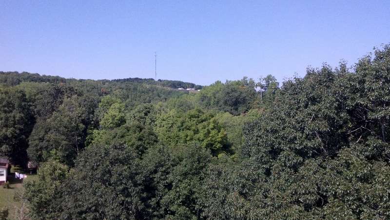
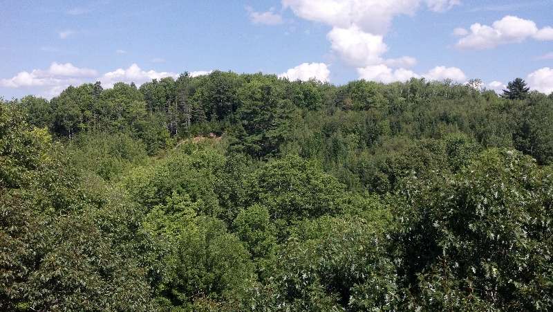
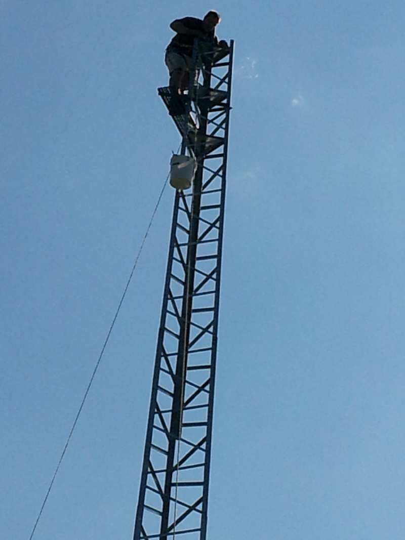
Well I actually made it up the tower today. I had hoped to get the 13B2's installed along with the 6m yagi but I had no ground support until after noon and then we got sidetracked for an hour or so so all I got done was get the tower rigged for installation. This being the first time to the top meant I had to do a lot of thinking about how to do things once on the tower. Thinking things out in advance is great but you still need to test your theories. So far all is good. Below are a few pictures of the view from the top.All pictures are from the top of the tower where the Explorer-14 will be mounted. This will serve 10-40m. The 12/17m yagi will be 5-6 feet above that while the 6m yagi will be about another 12 feet higher than from where the pix were taken. The topmost 13B2 will be 17 feet higher than from where the pix were taken with another one 10 feet below it.Even with less than perfect views the TOA should clear the hills easily.
This is looking north towards Indonesia and Western Australia. Apologies for the dark blurs in some pix. I keep forgetting where the lens is on the phone camera. No way I was taking my digital SLR camera up the tower.Note the top of the power pole at the bottom of the image.

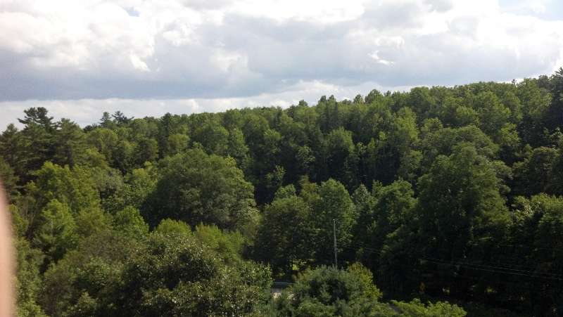
Looking north-northeast towards India and Southeast Asia
Looking East towards all of Africa. It looks worse than it is really. After that it is all water the rest of the way.
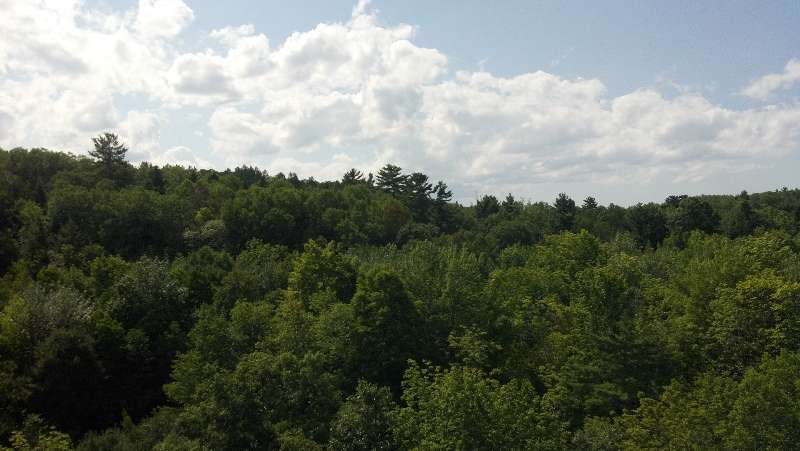
Looking south to all of South America.
Looking West towards USA,South Pacific and Eastern Australia and New Zealand.
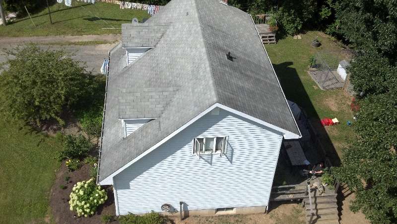
Just for perspective looking down at the house which is two stories.
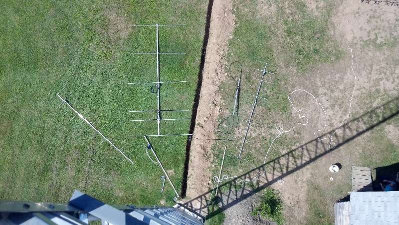
Looking straight down. The antenna on the left is a 13B2 with 15 foot boom and the larger yagi is the home brew six element 6m yagi on a 17 foot boom.
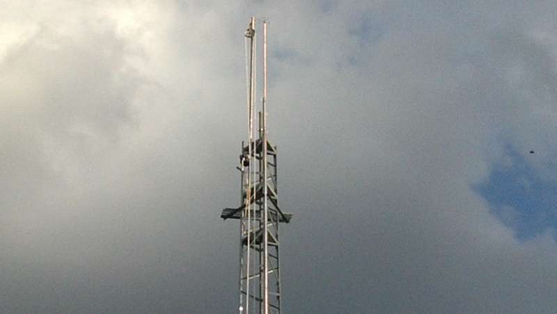
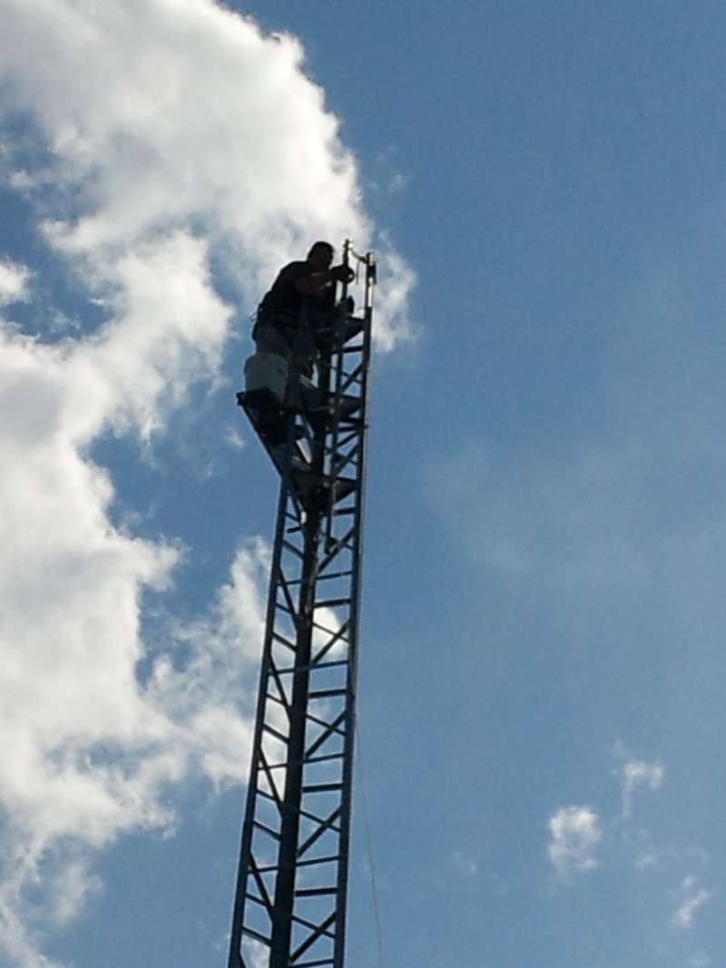
Top of tower rigged with dual purpose gin-pole and static dissipator on top of mast. The dissipator consists of a six foot length of 3/4 copper pipe with stainless steel cable frayed at the top to create dozens of sharp points for static to bleed off from. The idea is to bleed static to prevent a strike and if a strike does happen to divert the energy away from the antennas which would likely suffer irreparable damage if hit directly. The dual purpose gin-pole has a pulley at the top for raising items to the top of the tower and a worm drive 3500 pound rated boat winch mounted at the bottom and spooled with 3/16 stainless steel aircraft rated cable that is used to jack the entire mast/antenna stack up or down as required.
Back to work tomorrow so no more work until the first of next week but it is FINALLY coming together.
This is looking north towards Indonesia and Western Australia. Apologies for the dark blurs in some pix. I keep forgetting where the lens is on the phone camera. No way I was taking my digital SLR camera up the tower.Note the top of the power pole at the bottom of the image.
Looking north-northeast towards India and Southeast Asia
Looking East towards all of Africa. It looks worse than it is really. After that it is all water the rest of the way.
Looking south to all of South America.
Looking West towards USA,South Pacific and Eastern Australia and New Zealand.
Just for perspective looking down at the house which is two stories.
Looking straight down. The antenna on the left is a 13B2 with 15 foot boom and the larger yagi is the home brew six element 6m yagi on a 17 foot boom.
Top of tower rigged with dual purpose gin-pole and static dissipator on top of mast. The dissipator consists of a six foot length of 3/4 copper pipe with stainless steel cable frayed at the top to create dozens of sharp points for static to bleed off from. The idea is to bleed static to prevent a strike and if a strike does happen to divert the energy away from the antennas which would likely suffer irreparable damage if hit directly. The dual purpose gin-pole has a pulley at the top for raising items to the top of the tower and a worm drive 3500 pound rated boat winch mounted at the bottom and spooled with 3/16 stainless steel aircraft rated cable that is used to jack the entire mast/antenna stack up or down as required.
Back to work tomorrow so no more work until the first of next week but it is FINALLY coming together.
Last edited:
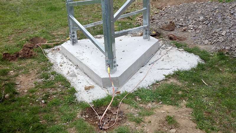
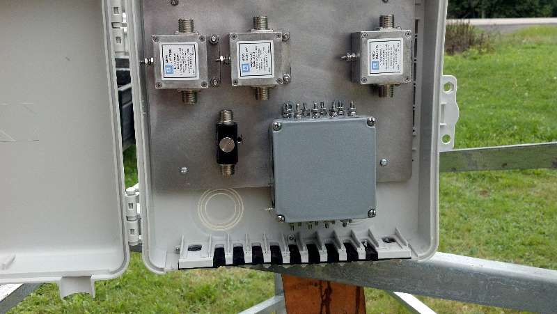
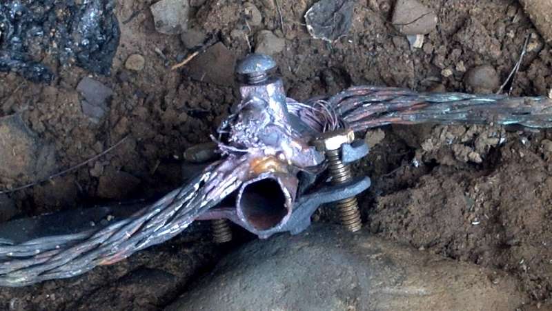
A few pictures of the ground system and Array Solutions lightning suppressors installed in a DX Engineering enclosure at the base of the tower to protect the coaxial cables and the rotator/antenna switch control lines. The copper bonding strap is four inches wide.
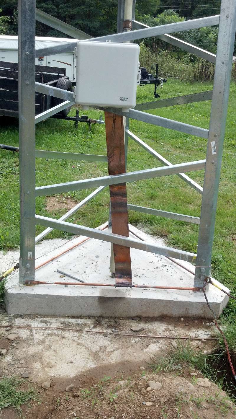
All copper ground rod connections are brazed using Selfoss rods which are a high temperature alloy containing copper and silver. The galvanized ground rods that had to be used in the shale bed are clamped securely.
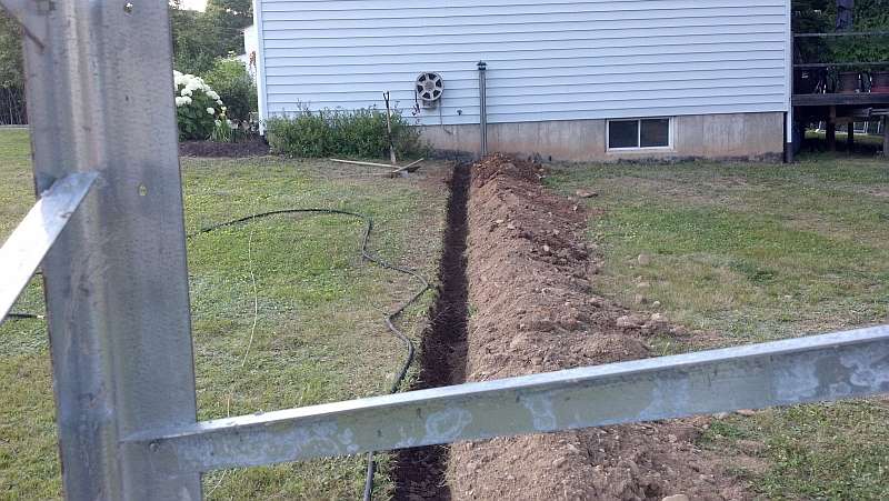
The bonding cable is equivalent to 3 gauge wire and runs from the tower to the cable entrance point where it then runs all the way around the house back to the cable entrance point again. Ground rods are placed around the house and the electrical service entrance gets tied to it as well.
Cable trench from tower to house.
All copper ground rod connections are brazed using Selfoss rods which are a high temperature alloy containing copper and silver. The galvanized ground rods that had to be used in the shale bed are clamped securely.
The bonding cable is equivalent to 3 gauge wire and runs from the tower to the cable entrance point where it then runs all the way around the house back to the cable entrance point again. Ground rods are placed around the house and the electrical service entrance gets tied to it as well.
Cable trench from tower to house.
I often wondered what it is that I am doing wrong when it comes to tower work. While I was risking life and limb doing this in sweltering heat:

And this:
My ground crew was busy doing this:
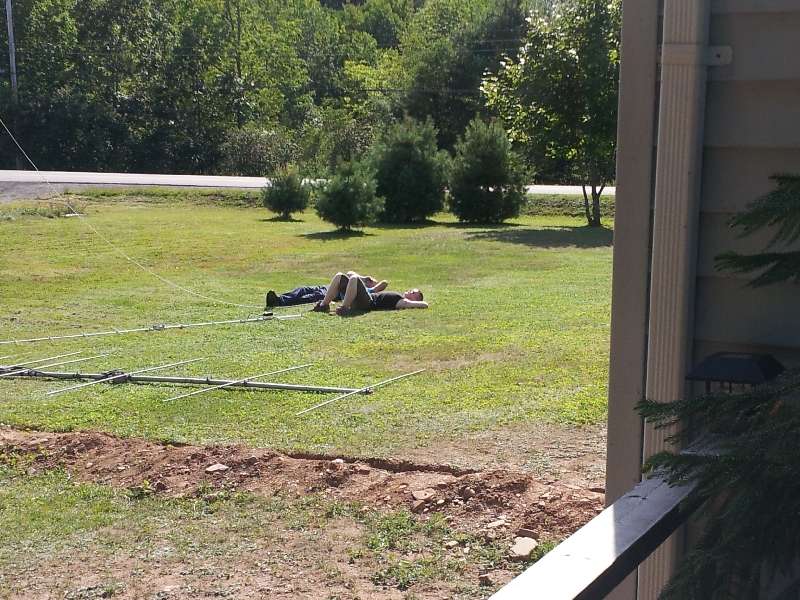

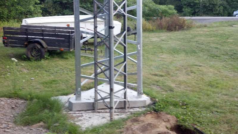
BTW just to show what I am upgrading from, here is a picture of the base section of my old 40 foot tower in front of the base section of my new 64 foot tower.The old one is 22 inches on a face at the bottom and only 9 inches at the top while the new one is 42 inches at the bottom and 18 inches at the top.
And this:
My ground crew was busy doing this:
BTW just to show what I am upgrading from, here is a picture of the base section of my old 40 foot tower in front of the base section of my new 64 foot tower.The old one is 22 inches on a face at the bottom and only 9 inches at the top while the new one is 42 inches at the bottom and 18 inches at the top.
Ya know Capt KW,
I've always neen told that tower work in the summer doesn't last. But winter tower work is good for decades.
I've always neen told that tower work in the summer doesn't last. But winter tower work is good for decades.
Ya know Capt KW,
I've always neen told that tower work in the summer doesn't last. But winter tower work is good for decades.
I've done enough of the former thank you. Time to try doing it the wrong way. LOL I figure it will be finished just in time for a good hurricane to hit us. Perhaps I should refer to the antenna stack as my storm magnet.

Congrats on your tower. I have been wanting a tower too. It'll be a while for me. Keep us posted on your progress.
dxChat
- No one is chatting at the moment.