These kind of antennas DON'T count on having a metal mast under them, but they do count on having a feed line connected to them which serves the purpose you contribute to the mast.
Those radials on a typical groundplane kit are more 'line isolators' than anything. They aren't of any particular use as a counterpoise, they just aren't resonant in the right frequency range.
Looking for definite, always true reasons for why a particular antenna 'works' better (for whatever reason) is a lot of wasted time when it get's to this point. You have to consider everything around that antenna as contributing to how it works, and that isn't going to be easy or simple. There'll always be something that you didn't account for.
- 'Doc
Doc, you seem to have a downer on GP kits for Antrons and Imax's. Don't you understand that using your mast or your coax as a counterpoise for any antenna is just simply taking a stab in the dark? Think of all the possible arrangements you could have with different masts, coax and so forth which could affect the performance of any antenna. Wouldn't it be great if we had an industry standard way of mounting antenna's so that they could all be compared with at least comparable parameters?
What is the point is suggesting that one antenna is better than another if mounting poles and coax location is too much part of the equation?
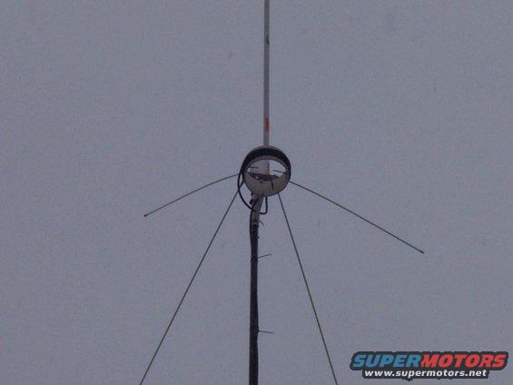
I've just mounted a custom GP kit on my Antron 99. The custom kit is a design that i've used before that myself and Bob-85 were tinkering with a couple of year ago - the imfamous spiderplane.
Firsty, to make sure we get all the currents we need flowing in the right places, I isolated the antenna from the mast. Not by taping the mast and mounting the antenna on the tape because this creates capacitance between the mast and the antenna. Isolated it by driving a piece of strong ash into the end of the mounting pole and mounting the antenna directly onto that. The antenna is choked with five turns of my RG213 on a four inch former, directly below the feed point. The GP kit bolts directly onto the base of the Antron about an inch below the tuning rings and consists of a 3 sided clamping system similar to the basket clamp on a Sigma 4.
There are three Sirio 827 radials attached to this but with a twist, the electrical length is increased to full quarter wave by attaching wire to the end of each radial which is aimed in free space towards the next radial tip and secured to it using strong nylon thread. The general shape of this kit if I were using four radials instead of three would resemble a swastika if you get what I mean. So its general sort of shape would resemble a three leg swastika with each leg secured to the next leg with nylon wire.
I will post pics up later.
When I first tried this method about two years ago on an half wave GP it worked tremendous and i had TX signal increases ranging from S2 to S4 over the standard GP. RX went up hell of a lot and I was hearing stations i'd never have dreamed of with the standard GP.
The Antron is a slightly different animal and seems to work better than a standard GP out of the box but it didn't stop me from trying to improve it.
An increase of one S point at 25 miles was my first result and an immediate increase in RX was apparant.
I worked 333 Tennessee and New Jersey yesterday from Central England using 5 watts when the skip was not very good.
Don't let anyone try to convince you that GP kits are not worth while, just make sure you Isolate the mast properly, choke it and get those currents flowing where we need them.
Nav 707 waving an hand.

