Some analyzers require 1/2 wavelength coax jumpers to display accurate results. So I’d like opinions around using solely 1/2 wavelength jumpers between meters,amps,drivers and radio. 1/2 wavelength multiples to antenna feed. Wouldn’t that insure your equipment will display more accurate readings and match up much more efficiently?

You are using an out of date browser. It may not display this or other websites correctly.
You should upgrade or use an alternative browser.
You should upgrade or use an alternative browser.
-
You can now help support WorldwideDX when you shop on Amazon at no additional cost to you! Simply follow this Shop on Amazon link first and a portion of any purchase is sent to WorldwideDX to help with site costs.
-
A Winner has been chosen for the 2026 July 4th Retevis RA89R Giveaway! Click Here to see who won!
Jumper length.
- Thread starter Jim5570091
- Start date
I believe the 1/2 wave on the analyzer output effectively causes the meter to read at the end of the coax. The coax doesn't influence the reactance to throw the meter off. And hooking the analyzer directly to the feed point isn't practical. So when trying to measure reactance, it can be important.
Some people use half wave coax between equipment, but it is not necessary. And besides, it would only be a half wave at one particular frequency. All the other channels, it would not be half wave so it would be pointless.
If the coax length affects your swr, you have other problems. Although people use different coax lengths to "fix" a problem, it is just masking the problem. Then again, if it's not a problem, then it's not a problem.
Chris

That’s exactly what I have heard. So my set up is lightning L6 quad, mfj meter Fed from x-force straight 10 pill, driven by tube amp and galaxy base radio. Changing lengths between any one of the four changes my meter results. Tower grounded well. What should I be looking for? As long as I keep 1/2 wave length jumpers in place it doesn’t change. I love this hobby just trying to understand what is going on. If that happens the coax is radiating and not all is radiated at the antenna is what I have read. Should I have some sort of choke at the feed point of the antenna?

The only time an electrical half wavelength multiple lengths of coax have to come into play is using older models of antenna analyzers. Many newer designs have the ability to calibrate out such things, so in that case length doesn't matter so much. Also, such coax lengths are only good for one frequency in said band, and moving away from that the results will be more and more off.
They actually still sell such antenna analyzers, such as the venerable MFJ-259 and 269. I would simply stay away from such devices as you can often get more capable devices for about the same price, or even cheaper (look up the nano-vna for example).
If your radio and or meter can't measure anything more than SWR then you don't have to worry about it as SWR doesn't change with coax length (short of losses in said coax). If you do notice your SWR changing with coax length, then you have another issue, like the common mode currents talked about above, or perhaps a ground loop. The easiest method of checking if you have such a problem is measure SWR, add a three foot jumper and measure again. If there is a noticeable difference, you have a problem.
Using such lengths for jumpers sounds at first like a good idea, but in reality, such things can actually hide other problems. I've seen cases where people would be "bitten" sometimes touching the radio, or even through the plastic housing of their microphone. I've seen other cases where the final stage transistors in radios, or the power transistors in amplifiers are blowing consistently. The cause of such problems were literally hidden by half wavelength multiples of coax.
There is actually a second use for coax length of electrical half wavelength multiples, that is your using off impedance feed-line aka 75 or 100 ohm coax on a 50 ohm radio setup. Although there really isn't a need for this in this day and age and I haven't heard of anyone needing something like this in forever.
The DB
Unlikely that you're seeing large CMC issues with that antenna, but a 1:1 CMC choke at the feedpoint using a Ferrite Toroid won't hurt and would prevent any pattern distortion caused by radiating coax.
7 3
7 3
Good sources for choke info/homebrewing:Would a choke help?
https://web.archive.org/web/20180422195858/http://www.karinya.net/g3txq/chokes/
http://k9yc.com/2018Cookbook.pdf
There's other sources out there as well, including ideas for winding ferrite chokes with coax or wire, enclosures, etc. Google will supply you with plenty of info. Everyone here hates QRZ.com but the antenna forum is a good source of real info on most things antenna. Real engineers.
7 3
I have home brewed several yagi and dipole antennas with out issues. But this one is being a beast. I think it may have to do with the matching stubs and the way it feeds a cubical quad with both vertical and horizontal polarization.
It's not a "cubical quad" in the classic sense. That antenna breaks the loop of a full-wave driven-element wire and feeds each end of the break with the coax. Might use a stub to bring the impedance down to 50 ohms. The driven element is a full-wave loop. The guy who came up with this design was having trouble with his yagi antenna in the Andes mountains. The thin air would break down and cause corona discharge at the ends of the dipole elements. Using a full-wave loop eliminated the pointy ends and the arcing problems.
This antenna uses what the original manufacturer Signal Engineering named "SFS" or Signal Feed System. The driven element is functionally two end-fed half waves in parallel. Grounding the coax braid to the boom and running the feed wire parallel to it makes the feed wire (and the boom) into a transmission line. And that's what matches the coax to the end-fed driven element.
I think. Had a PDF of the patent years ago. Not sure what became of it. First time someone tried to describe it to me I just didn't get the picture. Then I had a fella down the state build me one of his 4-element clones of this design. Uses wires instead of rigid rods. Never have seen this trick in any antenna book. Turns out books on ham antennas don't cover everything.
Who knew?
73
Yes sir. I have read that story. They still supply parts for this antenna. The driven element where the stubs are connected uses stainless steel bolts that pass through the fiber glass spreaders. This makes the whole cube electrically common. This is the design I’m a bit puzzled about. I have found a lot of information about the design with the help of wwdx community. Even contacted the manufacturer. Every thing I have read on antenna theory points to the antenna itself causing this. I have tried everything I had in my play book to get a SWR below a 1.5 in the center of the band. 1.5 on channel 20. Ch 1 and 40 rises to 2. Add power and that seems to go up.
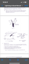
 Here is what info I have on the antenna. If the 1/4 directly connect to the matching stubs is supposed to be isolated from the remaining 3 sides of the cube it makes no mention of it. If it is supposed to be isolated that would explain a lot.
Attachments
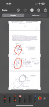

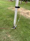
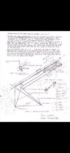
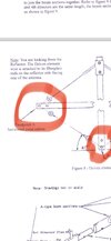
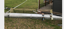
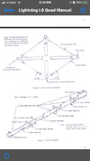
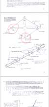
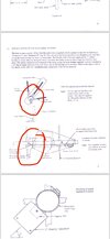
Image 8411 doesn’t match the factory drawing. But has been corrected it’s an old picture. But results remained the same either way.
dxChat
- No one is chatting at the moment.