• You can now help support WorldwideDX when you shop on Amazon at no additional cost to you! Simply follow this Shop on Amazon link first and a portion of any purchase is sent to WorldwideDX to help with site costs.
  • A Winner has been selected for the 2025 Radioddity Cyber Monday giveaway! Click Here to see who won!

Kenwood TS440S Too high voltage in VCO 5 (7.8v versus 5v)

Nodens - Thanks for heads up on D13. I did retest it before putting back in my reconstructed efforts. 1.8v forward in one direction only using my DMM diode test mode, ie passes the diode test.

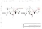
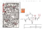
Dr. Frankenstein - Thanks for the heads up on extra detail. I was having a look at that as I could see part of TP11 circuit is outside the VCO 5 'fence'. I tried disconnected the FMD connector while running - no change to any of my last published voltages. I also just put R146 back in today.
Tested (OK) out of circuit at expected 22k ohms and I can see the 22k ohms when testing the trace once reinstalled. I think I will recap c180 and c182 (tantalum) as I did the two electrolytics inside the VCO 5 fence ie C185,C191

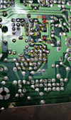
Brandon - Re soldered the area again your circled, cleaned all extra flux off, in that above picture the clear fluid is contact cleaner spray - I tried wetting the surface thinking it would take a better pic but its reflection make its harder to spot faults on edges etc. I also scrubbed the whole VCO 5 down with a toothbrush and contact cleaner spray (all I had on hand). Cool idea to flip that pic - why didn't I think of that!. I cant see any bridges under a loupe. Still same voltages after re soldering it all again. Thanks as always bro.

R146 (tested ok at 22k) has the 4.6-4.8v on both ends once reinstalled.

Thank you so much everyone for helping me - as someone who is pretty slow with this stuff I think I just need to keep trying. I appreciate the patience you have with me as a beginner.
 
  • Like
Reactions: Tech5
Been looking at it again today, 4.68v on each end of R146 while still showing 7.8v still on TP11.

Just trying to work through everything you said to me from your previous posts.

I also removed C180 (10uf 50v electro) and it tested at 4.7uf so I just put in what I had on hand, a 10uf 25v until I order the correct volt cap. Still producing 4.68v on R146 when I put the board back in.
 
The top circled lead is R146, where you say you have 4.8v. The bottom circled lead is the left side (schematic) of L40, which is TP11, where you say there us 7.8v. The foil connects these two points. If you have a different voltages on these two points, there is a no contact. I'd bet you have a bad solder joint right at TP11. Perhaps TP11 was banged around enough being probed and tore the pad around the solder, giving the impression it reflowed but is still broke. You may have to scrape some mask off and resolder that.

As for the 7.8v, I think I might know what's going on, Calbe Guy and I just encountered a similar issue. I'd bet C187 and D14 are rectifying the RF from the tank. Don't worry about that, it should drop when the connection is repaired.
 

Attachments

  • badjoint.png
    badjoint.png
    2.3 MB · Views: 78
Last edited:
  • Like
Reactions: Ghetto
Well I just soldered a wire directly from TP11 to R146 as per your pic. Put it back in and now 4.7v on each side of R146, still 7.8v on TP11. Same trace and different voltage on each end - its messing with my head.
20250820_160747.jpg
 
I was thinking about the rectified RF too but 7,8 volts RMS? I Really have a hard time to see that happen though. Good to see that you now have 4,68 volts on both sides of R146, but sadly still 7,8 volts on TP11 which seems to me, IMHO, impossible unless the wire you soldered is in the wrong place, IE not at TP11, R146 or the wire is not in contact with the TP and if so ... how can it still be 7,8 volts?

What voltage do you get, if it is possible to reach, at L40? If 7,8 volts I might be wrong about the RF not being rectified.

Even if there is 7,8 volts at R147 I can hardly believe that there is 7,8 volts at TP11 since you bridged the trace to R146, so I think we would have to agree that there are some misunderstandings here, but I could be terribly wrong and at the time of writing I do not know what to look for and with that being said ... I may have misunderstood something. I made som schematics, which I like a lot, where you can see how I look at it and BTW Ghetto; you are doing real great!

What is written above is just an old man's thoughts before breakfast and his first cup of coffee.
 

Attachments

  • TS440.jpg
    TS440.jpg
    300.1 KB · Views: 69
Last edited:
Yes, my fault @brandon7861 and now I see; thank you for clarifying that! I did not take my time to look at the layout of the board but now I did.
The foil connects these two points. If you have a different voltages on these two points, there is a no contact. I'd bet you have a bad solder joint right at TP11. Perhaps TP11 was banged around enough being probed and tore the pad around the solder, giving the impression it reflowed but is still broke. You may have to scrape some mask off and resolder that.
Well, I think you could be spot on here Brandon7861.

@Ghetto measure ohms as in the picture of the PCB and please, only on the leg of R146 as well as D14 cathode and let us know what you get.
 

Attachments

  • PCB.jpg
    PCB.jpg
    776.7 KB · Views: 63
I was thinking about the rectified RF too but 7,8 volts RMS? I Really have a hard time to see that happen though.
Not RMS, its DC, so that means 7.8v peak, which isn't unrealistic for a lightly coupled tank circuit. When we spotted this rectification happening in another radio, it was charging a tantalum cap to 5v from a tank attached to a transistor base biased to only 1.95v and a supply of 8v.

At this point, I would do some DC measurements without the oscillator powered. No RF, no confusing rectification. Ohm between R146 and D14's cathode to verify continuity.

And you just beat me to it lol, was just typing the same thing!
 
  • Like
Reactions: Ghetto and Tech5
Thanks for the support as always.

Brandon: R147 (tested OK) has 4.3v on its left leg as per pic (R146 has 4.7v both sides) Its mounted vertically so I cant prob the TP11 trace side without soldering on a fly lead?:

VCO5 R147 4.3v.png


Tech 5 and Brandon: And results of ohms test from D14 cathode to R146. Nothing out of ordinary other then L40 has 0.6 ohms + 0.3 ohms DMM leads = 0.9 ohms as per your diagram I've filled out. The L40 0.6ohms is the only thing adding resistance. I cant see an any anomaly when testing resistance between component legs tied to the TP11 trace either.

D14 tests OK in circuit.

PCB.jpg

Thanks for the encouragement. I do get a bit flat sometimes with this when I know you guys would probably sort it within 5 minutes if it was on your desk!
 
Last edited:
I wonder if your volt meter is adding enough capacitance to the VCO tank that the phase detector output has to hammer it with max voltage while the meter is connected in an attempt to bring the capacitance back down.

What kind of meter are you using?

Edit: You could test this with a separate volt meter and monitor R146's voltage at the same time you attach the suspect meter to TP11. I suspect the voltage at R146 will rise to 7.8v the moment TP11 is probed.

Edit again: but that would only make sense if you have been using the wrong side of L40 as TP11. This sounds unlikely, but I am running out of ideas.

L40 is a coil, so from a DC measurement perspective, I can see trying to probe either side. But in this case, one side is affected by probe capacitance, the other side is not because RF can't see the other side. Be sure you are probing the side of L40 with the black dot.
 
Last edited:
  • Like
Reactions: Ghetto and Tech5
Edit again: but that would only make sense if you have been using the wrong side of L40 as TP11. This sounds unlikely, but I am running out of ideas.
I wonder if your volt meter is adding enough capacitance to the VCO tank that the phase detector output has to hammer it with max voltage while the meter is connected in an attempt to bring the capacitance back down.

Yeah that is a good one @brandon7861! What would happen if L40 is soldered (turned 180 degrees) with what should be TP11 towards D14?

I find it highly impossible to see two different voltages on R146 and TP11 unless L40 is soldered wrongly, but looking at pictures of the PCB it seems that the solder joint (the side towards D14) is old and if so - and maybe in this case - that might have happened at the factory. Maybe we are chasing a fault that is somewhere else? :X3:

@Ghetto could you please have a look at L40 to see if it is misplaced in relation to the silkscreen - if there is one?
 

dxChat
Help Users
  • No one is chatting at the moment.