
You are using an out of date browser. It may not display this or other websites correctly.
You should upgrade or use an alternative browser.
You should upgrade or use an alternative browser.
-
You can now help support WorldwideDX when you shop on Amazon at no additional cost to you! Simply follow this Shop on Amazon link first and a portion of any purchase is sent to WorldwideDX to help with site costs.
-
A Winner has been chosen for the 2026 July 4th Retevis RA89R Giveaway! Click Here to see who won!
Looking for an RF coil for Galaxy DX 2527 (RCI 2950)
- Thread starter PoDuck
- Start date

still should be seeing more obviously! So check the pre-driver and work towards the driver for the finals you should see in excess of 1 to 2 volts on the base of the driver just quickly looking at the other posts it looks like most of the voltage reading is in the ballpark, but the readings you just posted are not if you use the scope to align the pre-stages you may be able to get a feel for what stage is not developing the way it should. I'm in a hurry right now as I must get moving here but see what happens in the pre-stages as it looks like they are not up to power.
Okay, I couldn't get a lock good enough on the collector of either final. The voltage kept drifting, and I would lose trigger before the image could be saved. Here are the images with the mirror board in place.
Base of driver

Collector of driver

Base of Q47

Base of Q47

Base of driver
Collector of driver
Base of Q47
Base of Q47
Voltages are actually quite low on all stages, both tx and rx. I'll see what I can find out.still should be seeing more obviously! So check the pre-driver and work towards the driver for the finals you should see in excess of 1 to 2 volts on the base of the driver just quickly looking at the other posts it looks like most of the voltage reading is in the ballpark, but the readings you just posted are not if you use the scope to align the pre-stages you may be able to get a feel for what stage is not developing the way it should. I'm in a hurry right now as I must get moving here but see what happens in the pre-stages as it looks like they are not up to power.
Post updated....review...
In fewer yes, please continue, we just have to find where it is sucking the signal away...start at the driver once you have it going...
Thank you for changing the 180 ohm resistors - the 0.46 volts or so is enough - let's get the finals to accept signal - keep the trimmers near their lower mA settings so if the radio fires up and the finals start to work, you don't have to scramble and refix the bias before the finals blow from too much bias current...
As far as signal - once the Driver "drives it" it goes thru L38 - that weird looking oversized ferrite bead with some wires attached coiled around it - look at the schematic I sent you - the coil is a coupling coil - it has one side driven by the driver, the other side "picks up" the RF from it and thru two caps C261 and C262 - they feed into the finals...
Remember the caps on the bottom of the board? Those should be relocated - they are to be set BEHIND in the bias circuit - not on the Bases of the Final. - They go behind the Ferrite Beads (L36 and L37 with the 1 ohm resistor on it) the caps FILTER that RF from screwing up the BIAS diode which can rectify it and re-inject them back into the bases of the Finals possibly damaging them by increasing the voltage drive you DID NOT set for and burn up the parts...(Those brown circles and where the open holes are on the top component side are where these filter caps go...)

Here's another concern of mine dealing with the 103 caps mounted on the bottom - they show X on the schematic, meaning they revised it and can be removed, I wouldn't I would keep them, just RELOCATE them AWAY from the Finals - they filter RF and noise from affecting BIAS - needs to be DC to keep it stable - The caps help to do just that...filter out RF that strayed in to the bias circuit...
Don't you just love autocorrect!
LOL all those typos are not typos - but it thinking what I should write - not what I wrote!
In fewer yes, please continue, we just have to find where it is sucking the signal away...start at the driver once you have it going...
Thank you for changing the 180 ohm resistors - the 0.46 volts or so is enough - let's get the finals to accept signal - keep the trimmers near their lower mA settings so if the radio fires up and the finals start to work, you don't have to scramble and refix the bias before the finals blow from too much bias current...
As far as signal - once the Driver "drives it" it goes thru L38 - that weird looking oversized ferrite bead with some wires attached coiled around it - look at the schematic I sent you - the coil is a coupling coil - it has one side driven by the driver, the other side "picks up" the RF from it and thru two caps C261 and C262 - they feed into the finals...
Remember the caps on the bottom of the board? Those should be relocated - they are to be set BEHIND in the bias circuit - not on the Bases of the Final. - They go behind the Ferrite Beads (L36 and L37 with the 1 ohm resistor on it) the caps FILTER that RF from screwing up the BIAS diode which can rectify it and re-inject them back into the bases of the Finals possibly damaging them by increasing the voltage drive you DID NOT set for and burn up the parts...(Those brown circles and where the open holes are on the top component side are where these filter caps go...)
Here's another concern of mine dealing with the 103 caps mounted on the bottom - they show X on the schematic, meaning they revised it and can be removed, I wouldn't I would keep them, just RELOCATE them AWAY from the Finals - they filter RF and noise from affecting BIAS - needs to be DC to keep it stable - The caps help to do just that...filter out RF that strayed in to the bias circuit...
This is what I meant by "Behind" the Ferrite beads - the circuit only applies a DC BIAS, a simple flat voltage, to keep the transistors as close to turning on as possible, without turning them on themselves. These caps keep stray RF from doing that - from reinjecting and re-rectifying thru the bias diodes, the diodes work like little detectors and can pick up stray RF. IT can leak past the ferrite beads and add extra power you didn't adjust for - even IF from the radios own internal circuits and add a voltage you don't want in there - and possibly damaging your work.
Okay, TP2 to center leg of both finals shows continuity and relatively no resistance. The resistors, 255 and 257, I switched out to 180 Ohm resistors as per your previous instruction, but they both are showing 8 V on one side and .45 V on the other. The rest of the resistors in that area seem to be fine.
Am I wrong in thinking I could make some headway if I follow the signal path from the driver to the finals and test for signal? I'm not sure which path the signal takes from the driver to the finals. It seems that since I do get a signal from the driver, however bad it is, it should conduct until wherever the problem is, and I should be able to follow it, if I knew the path. It might be that it is being pulled down somewhere, or it could be an open circuit, but either way, that is what I am thinking about.
Don't you just love autocorrect!
LOL all those typos are not typos - but it thinking what I should write - not what I wrote!
Last edited:

Well, I wasn't able to do as much today as I thought I might. I had a DJ and a guitarist both come in today wanting a rush job on repairing their equipment, so the Galaxy had to go back on the shelf. I'm hoping I'll be done later tonight or early tomorrow, so I can get back to working on it.
I will update this when I get back to it.
Thanks again.
I will update this when I get back to it.
Thanks again.
I pulled those old caps and put new ones in those spots. The old ones were kind of hammered after me pulling them and replacing them so many times while messing with this.Remember the caps on the bottom of the board? Those should be relocated - they are to be set BEHIND in the bias circuit - not on the Bases of the Final.
The strange thing is, it is acting like it was when the anode of one of the diodes was grounded, but I have tested the resistance on the anodes, and the finals both read 17.5 ohms, and the driver reads around 3K, so no dead short this time.
Anyway, I'm still getting negative voltage at the bases of the transistors. I remember reading somewhere that for class AB, voltages should be E<B<C, but right now, since the bases are negative, I am getting B<E<C. What would be pulling my voltage on the base negative?
That would possible the diodes are rectifying the RF showing negative.
That may indicate the bias side of the base feed - the bias and the RF meet at the base - so if the Bias circuit is goofed up - the diodes will rectify (due to their direction) and SHOW NEGATIVE.
Be careful here, because the base region can fail due to the diodes negative voltage
The Pinout for a 2312 like you got, is B C E - Base Collector Emitter
That negative reading should occur only in AM mode.
You should see about 6/10 of a Volt POSITIVE polarity on the base leg of the driver and finals while keyed in a SSB mode with the mike gain at zero.
But in AM mode, the drive carrier gets partly rectified by the transistor's base-to-emitter junction. Put a meter with a "diode test" feature across base and emitter of a loose transistor and it will show you a proper diode reading. This is a parasitic (accidental) feature of the transistor's internal structure.
Once the RF drive level to the transistor's base terminal is high enough, part of the RF's AC waveform gets rectified by that 'accidental' diode built into the transistor's base terminal. In this case, a diode with the cathode grounded.
A negative DC voltage is what you should see if you feed enough RF carrier into one of those.
Has to be a higher RF voltage than the diode's forward-bias drop. In the case of a bipolar driver or final, that's around 6/10 of a Volt.
73

I was curious if he ever found the L34 P/N ECRFZ0001 0.23uH coil he was needing, I'm in need of one as well. Barkett has the L33 for the 99V P/N ECRFZ10045 0.16uH core and wondered if he used the one that Barkett sold one, I guess i could contact Greg and see if his 0.16uH coil would work in place of the 0,23uH coil i need.
Last edited:
If you have a nanoVNA, you can look at the adjustment range on similar inductors. As long as the core come from the output of an 11m radio, the mix shouldn't be an issue, but you might need to change the number of turns on it to match what you need.
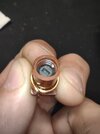
I just grabbed a random one that looked close thinking I would rewind it for that inductance but it was already there") Its hard to see the marker there at the top but with a little turn I got the reactance to 39.1Ω (which at 27.125MHz is .23uH).
Its hard to see the marker there at the top but with a little turn I got the reactance to 39.1Ω (which at 27.125MHz is .23uH).

Want it? PM me if this looks like it will work. I'm going to the post office tomorrow. EDIT: added better pic below
I just grabbed a random one that looked close thinking I would rewind it for that inductance but it was already there
Its hard to see the marker there at the top but with a little turn I got the reactance to 39.1Ω (which at 27.125MHz is .23uH).Want it? PM me if this looks like it will work. I'm going to the post office tomorrow. EDIT: added better pic below
Attachments
Last edited:
Thank's for the offer Brandon, I found a old 2950 in my donar pile and stole it outta there,
dxChat
- No one is chatting at the moment.