• You can now help support WorldwideDX when you shop on Amazon at no additional cost to you! Simply follow this Shop on Amazon link first and a portion of any purchase is sent to WorldwideDX to help with site costs.

Messy Maco 750 resurrection

Danzik

Active Member
Oct 18, 2022
182
10
28
45
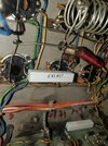
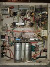
Hi, I recently got ahold of a Maco 750 that is in need of great help as it has several issues I am aware of, one of them is, there is a white wire coming from the large capacitors that is carrying 450 VDC that had come off from wherever it is supposed to go ? anyone know off hand? It goes somewhere around the driver tube sockets somewhere because there was a wire tie on it. This amplifier had 4 Maco M-2057, 3- 8950, and one 6LF6 tube in it when I got it, I have no idea why the 6LF6 is in there because I measured 14 volts on all the heater pins on the tube sockets ‍♂️ another mystery to me is that the tube heaters will not light up on the driver tubes even though I tested the heater pins and they have 14 volts and the heaters in the tube are fine, would a shorted or bad coupling capacitor on the tube socket cause it not to light up ? Thanks
 

By the way, the two drivers are wired for 6LB6 and do light the heater when both tubes are inserted, so that now makes sense
 
Here is the 450vdc wire that was loose that I was referring too, would it make sence that it goes to pins 3 and 11 on the 6LB6 driver tubes perhaps ?


17013761123376813445107769185151.jpg
17013762593276870555547618699590.jpg
 
The exploded glass neon bulb at the other end of that wire tells us this was the screen-grid wire for the pre driver stage. It was configured to hold the carrier down. When the drive signal was modulated, it would cause enough current drain from the screen grid to drop screen voltage across that 100k 2-Watt resistor. When the voltage drop reached around 80 Volts the gas in the neon lamp would fire, holding the voltage drop more or less constant. This would goose a high screen-grid current only during modulation peaks, but reduce it for just the carrier drive alone. This would exaggerate forward swing, at the expense of audio clarity.

The screen current for that tube was usually high enough to overheat and wear out the neon lamps. Nobody asks how long this kind of amplifier will last, they just want to know what the wattmeter shows. Creates an incentive for the builder to provide a high meter reading at the expense of service life.

This setup is a bit like a nitrous bottle without an "off" switch.

73
10-4 Nomadradio, I kinda understand this, I also have a 1kw golden Eagle " the black one" sporting the incorrect 20LF6 tubes and it also uses this neon design and one bulb is burnt out of it also but has been performing fairly well the last couple years. What is your advise on the Maco just to get it going ? What specs are the neon to replace it does it matter which bulb ? And does this screen voltage wire go across pins 3 and 11 on both the 6LB6 driver tubes then ? thanks a ton
 
It kinda looked like the wire would have been attached between where the pencil point is and the blue pair of resistors above it which would span between pins 3 and 11 on the 6LB6 tubes ?
 
But then according to the data sheet for the 6LB6 pin 11 is internal and not to be used but pin 3 is the screen grid Screenshot_20231201-070556_Drive.jpg
 
Yeah, pin 3 is the screen grid connection they claim to provide. An internal jumper to pin 11 is something the calibrated eyeball can check to see if it's there. Some type numbers specify them. Others don't, but still have one in there. Never quite understood the practice of marking a tube pin "IC" or internal connection.

Internal to what?

73
 
Well, I got her going at least ! I am pretty happy about that ! Nomadradio, I did clip off pin 11 on the driver's just to be safe "6LB6 " it is putting out 500 watts on high which isn't bad considering one of the 6LB6 driver tubes don't even register on my tube tester but I have a good one ordered, all the 2057 that I have also tested low around 45 on a B+K 747 tester but I was testing them as a 8950 because the 2057 is not in the test sheets so they might actually be stronger than that ‍♂️ anyone know about that ?
 
Yeah, I spoke to soon however, it was working fine but later when I turned the unit back on, only warming it up,it had destroyed a tube which is not good as it was a 8950 the plate voltage on the tube cap is 510 VDC, that sounds right doesn't it ? I checked it for AC voltage to and there was only 32 volts present. I did not replace those neons yet but I am also wondering about those 2 large capacitors for the screen voltage, there was no red plating or anything going on and when I talked on it earlier it was putting out decent wattage, I dunno I am lost, I may want to replace those old carbon resistors on the tube plate caps to perhaps ‍♂️
 
510 Volts is Low-Side voltage.

Was this a driver tube? Or one of the six final tubes?

We have seen folks who blew up too many driver tubes change the driver high-voltage hookup to run from the low side B+ all the time, only switching the final tubes on the High/Low switch.

Any tube amplifier that old could have any number of modifications in it by now.

The parasitic-choke resistors on each plate cap are at the bottom of the list of suspects to cause major trouble.

73
Hi Nomadradio, yeah I didn't flip it to high before, Driver- low 505 VDC high 1012 VDC ,,, Finals- low 512 VDC high 1026 VDC. Screen voltage on all is 503 VDC thanks for your help ! When the 8950 blew I was looking right at it and the amplifier was in standby mode and I heard a pop and a couple sparks come from the plate cap externally on the top of the tube ! I let the caps bleed off and took the tube to the tester and no reading at all, no short, no grid leakage and no movement of the needle but the heater was lit up.
 
I might also add that someone had put a power resistor on one of the pin 9 in the final section "Grid 1" when there is still a old carbon style 2 watt on the tube socket right beside it that tests bad at 526 ohms, was supposed to be 1k not sure if leaving that old one in there would affect the grid ‍♂️
 

Attachments

  • 17017308706197073265022308970675.jpg
    17017308706197073265022308970675.jpg
    1.8 MB · Views: 47
  • 17017309432575055638975723734979.jpg
    17017309432575055638975723734979.jpg
    2.3 MB · Views: 42
I am getting - 13.81 vdc on Pin 9 "grid 1" on the final 8950 section
 
Last edited:

dxChat
Help Users
  • No one is chatting at the moment.