• You can now help support WorldwideDX when you shop on Amazon at no additional cost to you! Simply follow this Shop on Amazon link first and a portion of any purchase is sent to WorldwideDX to help with site costs.

Messy Maco 750 resurrection

The plate of the 8950 tube is not supposed to "cherry", or give off any light from the surface, not even dull red.

The 8950 has an internal jumper joining pin 5 to pin 9. This is the control-grid pin where negative bias is applied. Either pin 5 or 9 works for that tube.

The 6LB6 has only pin 5 connected to the control grid. A jumper wire across each tube socket from pin 5 to pin 9 would make the socket work for either tube type. Sounds to me as if the connection has been made only to pin 9 on one or more of the tube sockets.

If that jumper wire is already there, probe pin 5 and make sure you have around 16 Volts DC, negative polarity. if you don't it's time to find out why.

73
 
  • Like
Reactions: Danzik
The plate of the 8950 tube is not supposed to "cherry", or give off any light from the surface, not even dull red.

The 8950 has an internal jumper joining pin 5 to pin 9. This is the control-grid pin where negative bias is applied. Either pin 5 or 9 works for that tube.

The 6LB6 has only pin 5 connected to the control grid. A jumper wire across each tube socket from pin 5 to pin 9 would make the socket work for either tube type. Sounds to me as if the connection has been made only to pin 9 on one or more of the tube sockets.

If that jumper wire is already there, probe pin 5 and make sure you have around 16 Volts DC, negative polarity. if you don't it's time to find out why.

73
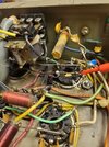
Ok Nomadradio, you may have hit the nail on the head, this box originally had 2 6LB6 driver tubes so they have the pin 5 to pin 9 connections, but the final tubes were originally 8950 and I swapped them to 6LB6 and they DO NOT have the pins 5 and 9 connected together and only have that blue wire on pins 9. Ok, here's a question would these final tubes being wired incorrectly like that throw off the negative bias on pin 5 like you told me to check then because I am not getting anywhere close to -16 volts on pins 5 on the driver tubes and they are the ones red plating, also at what point should pin 5 have the -16 volts ? Is this on keyup or even with the amp on and in standby? Thanks a bunch for your help as I greatly appreciate it !
 
17052529538031531633873106410527.jpg17052530520065094354113631401593.jpg
 
The plate of the 8950 tube is not supposed to "cherry", or give off any light from the surface, not even dull red.

The 8950 has an internal jumper joining pin 5 to pin 9. This is the control-grid pin where negative bias is applied. Either pin 5 or 9 works for that tube.

The 6LB6 has only pin 5 connected to the control grid. A jumper wire across each tube socket from pin 5 to pin 9 would make the socket work for either tube type. Sounds to me as if the connection has been made only to pin 9 on one or more of the tube sockets.

If that jumper wire is already there, probe pin 5 and make sure you have around 16 Volts DC, negative polarity. if you don't it's time to find out why.

73
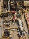
Also, I just looked at the 6LB6 data sheet again and it says internal connection for pin 9 so I grabbed the ohm meter and checked for continuity between pin 5 and pin 9 on a 6LB6 and it did have continuity within the tube ‍♂️ so would it make a difference????
 
If the connection between pins 5 and 9 is there, it's all you should need. Doesn't matter what the data sheet says. But putting a jumper from 5 to 9 should avoid surprises later if that tube gets changed.

73
The connection between 5 and 9 on the socket tubes is there on the 2 driver tube sockets but not the final sockets, however if I use a continuity tester on the 6LB6 tubes between pin 5 and 9 the meter beeps and shows continuity. But it is the driver tubes red plating, should I have that -16 volts negative bias voltage you were talking about with the amp on and just in standby because I do not ! Or do I take that measurement with the amp keyed up ?
 
I should also mention that the driver tubes do not start to red plate until keyup, either way I do not believe the negative bias is present
 
If the connection between pins 5 and 9 is there, it's all you should need. Doesn't matter what the data sheet says. But putting a jumper from 5 to 9 should avoid surprises later if that tube gets changed.

73
Since I swapped from 8950 finals to the 6LB6 tubes I will take wire on the socket pins from 5 to 9 as it won't hurt anything anyways
 
driver tubes do not start to red plate until keyup,

I would start by removing the voltage source from the screen grid pin 5/9 lugs on the driver tubes. A temporary wire from each tube's screen pins to ground will probably stop the 'cherrying' behavior of the tubes.

Any time the screen grid has more than 16 Volts on it, the negative bias to the control grids must also be increased. Grounding pins 5 and 9 should get you a starting point that doesn't threaten the life of the tubes. As a rule, increasing the voltage on pins 5/9 above zero increases power gain, and also increases the negative grid voltage needed to control tube current to a safe level.

If it is stable with those pins grounded, you can then decide how much you wish to "hot-rod" the driver stage for more power gain. My advice would be to leave the driver tubes' screen grids at zero volts and enjoy longer tube life.

73
 
  • Like
Reactions: Danzik
I would start by removing the voltage source from the screen grid pin 5/9 lugs on the driver tubes. A temporary wire from each tube's screen pins to ground will probably stop the 'cherrying' behavior of the tubes.

Any time the screen grid has more than 16 Volts on it, the negative bias to the control grids must also be increased. Grounding pins 5 and 9 should get you a starting point that doesn't threaten the life of the tubes. As a rule, increasing the voltage on pins 5/9 above zero increases power gain, and also increases the negative grid voltage needed to control tube current to a safe level.

If it is stable with those pins grounded, you can then decide how much you wish to "hot-rod" the driver stage for more power gain. My advice would be to leave the driver tubes' screen grids at zero volts and enjoy longer tube life.

73
10-4 Nomadradio I will definitely try this and get back with you with the results, I am also thinking about installing a metal mesh screen between the drivers and final tubes on this because they are very close together, like alot of you have done on the Maco 300
 
I would start by removing the voltage source from the screen grid pin 5/9 lugs on the driver tubes. A temporary wire from each tube's screen pins to ground will probably stop the 'cherrying' behavior of the tubes.

Any time the screen grid has more than 16 Volts on it, the negative bias to the control grids must also be increased. Grounding pins 5 and 9 should get you a starting point that doesn't threaten the life of the tubes. As a rule, increasing the voltage on pins 5/9 above zero increases power gain, and also increases the negative grid voltage needed to control tube current to a safe level.

If it is stable with those pins grounded, you can then decide how much you wish to "hot-rod" the driver stage for more power gain. My advice would be to leave the driver tubes' screen grids at zero volts and enjoy longer tube life.

73
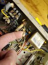
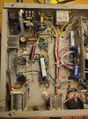
Hi, this is the only wire feeding pins 5 and 9 on the driver sockets and it is coming from that input tuning coil or is it a bias adjustment coil ??? Is it safe to go ahead and disconnect there from that disc capacitor and put that wire to ground then as it connects all 4 pins in that driver section?
 

Attachments

  • 17054484129873991155100998653530.jpg
    17054484129873991155100998653530.jpg
    1.6 MB · Views: 26
  • 17054485200665648644629284153575.jpg
    17054485200665648644629284153575.jpg
    1.6 MB · Views: 27
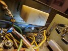
There is also this 1/4 watt resistor right underneath the preamp relay that looks kinda burnt I am not sure what it is for but I do know the preamp works in this box, just somthing I thought I would mention, but yeah let me know if it is ok to disconnect that coil from pins 5 and 9 if so I will try grounding that wire and see what happens and go from there
17054497737497886667692977638039.jpg
 
Ohhh, No MR Bill!

Maybe that reference is from too many decades ago.

I relied on memory rather than glancing at the tube's base diagram before putting my foot in my mouth.

Pins 5 and 9 are the CONTROL grid, not the screen grid. Pins 5 and 9 must have the negative bias voltage applied at all times.

Pin 3 is the one I was thinking of. That IS the screen grid, normally grounded, or a positive voltage applied to it.

I was guessing that the voltage on pin 3 was too high.

Removing a positive voltage source from pin 3 and connecting pin 3 (not the voltage source) to ground should calm down the driver tubes so they won't overheat and risk permanent damage. Thought I had seen a fairly high positive-voltage reading back up the thread. Grounding pin 3 should calm it down if you have positive DC voltage there now.

Oops......

73
 
Last edited:
  • Wow
Reactions: lonestarbandit
Ohhh, No MR Bill!

Maybe that reference is from too many decades ago.

I relied on memory rather than glancing at the tube's base diagram before putting my foot in my mouth.

Pins 5 and 9 are the CONTROL grid, not the screen grid. Pins 5 and 9 must have the negative bias voltage applied at all times.

Pin 3 is the one I was thinking of. That IS the screen grid, normally grounded, or a positive voltage applied to it.

I was guessing that the voltage on pin 3 was too high.

Removing a positive voltage source from pin 3 and connecting pin 3 (not the voltage source) to ground should calm down the driver tubes so they won't overheat and risk permanent damage. Thought I had seen a fairly high positive-voltage reading back up the thread. Grounding pin 3 should calm it down if you have positive DC voltage there now.

Oops......

73
That's ok Nomadradio, I thought that seemed kinda odd That's why I wanted to confirm that with you before I tried that procedure, yeah you may have very well seen higher voltage on Pin 3 earlier in this thread, I will check it out tomorrow and go from there ! Thank you very much for your help !
 

dxChat
Help Users
  • No one is chatting at the moment.