Pin 3 the screen voltage has 510 VDC on itOhhh, No MR Bill!
Maybe that reference is from too many decades ago.
I relied on memory rather than glancing at the tube's base diagram before putting my foot in my mouth.
Pins 5 and 9 are the CONTROL grid, not the screen grid. Pins 5 and 9 must have the negative bias voltage applied at all times.
Pin 3 is the one I was thinking of. That IS the screen grid, normally grounded, or a positive voltage applied to it.
I was guessing that the voltage on pin 3 was too high.
Removing a positive voltage source from pin 3 and connecting pin 3 (not the voltage source) to ground should calm down the driver tubes so they won't overheat and risk permanent damage. Thought I had seen a fairly high positive-voltage reading back up the thread. Grounding pin 3 should calm it down if you have positive DC voltage there now.
Oops......
73

You are using an out of date browser. It may not display this or other websites correctly.
You should upgrade or use an alternative browser.
You should upgrade or use an alternative browser.
-
You can now help support WorldwideDX when you shop on Amazon at no additional cost to you! Simply follow this Shop on Amazon link first and a portion of any purchase is sent to WorldwideDX to help with site costs.
-
A Winner has been chosen for the 2026 July 4th Retevis RA89R Giveaway! Click Here to see who won!
Messy Maco 750 resurrection
- Thread starter Danzik
- Start date
Pretty sure the burned resistor is in the keying circuit. The first time someone drives it with too much power, a resistor burns. Sometimes only the paint layer burns, and the resistor still tests okay.
73
73
There's your problem!Pin 3 the screen voltage has 510 VDC on it
To feed that kind of positive voltage to pin 3, the negative bias on pins 5-9 would have to be ten times higher or more.
Yeah, ground pin 3 on the driver tubes. Should calm things down just fine.
73

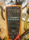
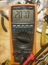
I tried it and grounded the screen grid pins and it worked but I was lucky to see 100 watts out of it so I wired it back up the way it was before and will start over. Ya know one thing I noticed last night after I keyed it down enough times and got it to start cherrying the plate I heard the hiss in my radio, there was no rx present as the tube was starting to redplate as if the relay had stuck during tx and I saw bright light under the amp and I think it was the neons, this would be oscillating wouldn't it ?????? Don't the tubes cherry if a oscillating situation happens ? The driver tubes are right on top of the finals like no other amp I have all others are located away and have a cage around them . The photo are of the negative bias off of pin 5 during keydown wouldn't that be enough negative bias with 500 volts on the screen ??? The other photo showing 2 volts is without the radio keyedThere's your problem!
To feed that kind of positive voltage to pin 3, the negative bias on pins 5-9 would have to be ten times higher or more.
Yeah, ground pin 3 on the driver tubes. Should calm things down just fine.
73
Attachments
But that -48 volts of bias was also under modulation I forgot to mention that but you said with that high of screen voltage the negative bias would have to be 10 times higher than the -16 volts and that's nowhere close, is it perhaps possible to use the screen voltage off of the final tubes for the drivers also ?
Gotta distinguish between the steady fixed negative control-grid voltage present in receive mode, and the dynamic (higher) negative control-grid voltage you'll read while keyed down and driving the amplifier with a AM carrier.
Not the same thing.
The control grid of the tube will act like an accidental rectifier when the amplitude of the drive waveform is high enough.
the drive from the radio feeds the tube's cathode, but what the tube "sees" is the difference between the cathode voltage and the control-grid voltage. The positive peaks of your drive waveform will make the grid's polarity compared to the cathode positive. This turns the grid into an accidental anode, having a voltage that's positive compared to the cathode.
But it's only for the tiny short bursts when each peak of your drive waveform passes that threshold. Those brief bursts of current get averaged out, and cause a current flow from grid to cathode. The textbook term for how this happens is called "grid-leak voltage". Never have wrapped my mind around how they came up with that name. Any time you see the term "grid current", with regard to large transmitting tubes and amplifier that use them, this is what they mean. A so-called "power grid tube" is designed to run with a lot of grid current. The 6LB6 tolerates some grid current.
You can always take a rectifier diode from the 12 Volt AC, with the banded end (cathode) feeding into a 2200uf 25-Volt filter cap to get about 16 Volts positive DC. Feed this into the screen grids instead of the high voltage it had on it. This should wake up the driver tubes a bit. I'm in the habit of putting a 10k 2 Watt resistor from the screen grids to ground, along with the positive 16 Volts. Just to prevent negative screen-grid current. Probably not a big deal, just an old habit.
73
Hi, I very well may try coming off the ac heater voltage with the diode and cap like you mentioned for the screen and try that out and see what happens! I was messing around with it a bit last night and noticed I have a - 104 vdc of negative bias on the wire coming directly off of that input tuner but then after it passes through that disk capacitor it goes positive to about 2 vdc then it goes to pin 5 on the drivers . Couldn't the cap value here be changed or done away with completely to get the desired negative bias ? Just asking questions here to learn more about it is allThere's your problem!
To feed that kind of positive voltage to pin 3, the negative bias on pins 5-9 would have to be ten times higher or more.
Yeah, ground pin 3 on the driver tubes. Should calm things down just fine.
73

Hmm. I may have completely misread the setup in this amplifier.
Oops.
This makes it sound like the grid-drive version. The driver tubes are not "grounded grid", with the radio's drive feeding the cathodes of the tubes.
The cathodes are grounded, and the tiny slug-tuned coil is stepping up the RF voltage from the radio, feeding it to the grids of the driver tubes.
Not the cathodes.
This would be the only reason to see more than 100 Volts negative DC in the amplifier. When driving the tube's grid, a DC bias voltage high enough to reach cutoff. This way the drive tubes draw no current until the drive carrier voltage is high enough. This technique was used in a variety of Black Cat brand amplifiers back in the day. If it's adjusted right, this trick will exaggerate the forward modulation power and reduce the carrier in proportion to the modulated peaks. The high screen-grid (G2) voltage gooses the tube's peak power, but makes a really high negative voltage necessary on the control grid (G1) to keep the tube current down to a safe level. Higher negative grid voltage equals lower plate current.
Still reminds me of holding a broom upside-down with the end of the handle in the palm of your upturned hand. Any imbalance and things fall down.
Should caught that detail earlier. Somebody needs to compose a conversion for those Maco amps back to grounded grid and post it on the web.
It's just more stable.
73
Probably so linearone, if I knew as much about them as you guys do anyways, but I don't but would sure like too. I just get a kick out of fixing these old boxes that are older than I am ! I enjoy it once and if I get it figured out anyways and learn somthing in the process, however I am having a rough time with this one . I have fixed several and got my confidence up but usually it's bad HV caps, bad keying circuit transistors, shorted coupling caps, relays, resistors out of spec and so on, but figuring out how these tubes work and biasing them I am having trouble withYou could have built a new amplifier in the time spent repairing this one.
Building tube based amplifiers is 95% metal work, specifically cutting holes just right and putting them in ideal locations. The electrical part is very little time honestly. I can build almost any size amplifier in about 16-24 hours working time. The wiring and tune up / optimization process is a couple hours at best . It's why when you start building for yourself, you realize aside from budget differences, it always pays to build bigger than smaller. It takes the same amount of time to build a 10,000 watt amplifier as it does an 800 watt amplifier. It's also the reason why a lot of builders can't build small amplifiers, there's no money in it. At least when you're doing home brew type building, which is what every cb amplifier is.Probably so linearone, if I knew as much about them as you guys do anyways, but I don't but would sure like too. I just get a kick out of fixing these old boxes that are older than I am ! I enjoy it once and if I get it figured out anyways and learn somthing in the process, however I am having a rough time with this one . I have fixed several and got my confidence up but usually it's bad HV caps, bad keying circuit transistors, shorted coupling caps, relays, resistors out of spec and so on, but figuring out how these tubes work and biasing them I am having trouble with
To be honest, you can open up almost any ARRL handbook and they usually can explain to you how to build an amplifier. At least a grounded grid triode. There's a lot less information available to build tetrodes . There's very few secrets left.
Last edited:
I would be very good at the sheet metal work, have alot to learn on the electronics part of itBuilding tube based amplifiers is 95% metal work, specifically cutting holes just right and putting them in ideal locations. The electrical part is very little time honestly. I can build almost any size amplifier in about 16-24 hours working time. The wiring and tune up / optimization process is a couple hours at best . It's why when you start building for yourself, you realize aside from budget differences, it always pays to build bigger than smaller. It takes the same amount of time to build a 10,000 watt amplifier as it does an 800 watt amplifier. It's also the reason why a lot of builders can't build small amplifiers, there's no money in it. At least when you're doing home brew type building, which is what every cb amplifier is.
To be honest, you can open up almost any ARRL handbook and they usually can explain to you how to build an amplifier. At least a grounded grid triode. There's a lot less information available to build tetrodes . There's very few secrets left.
https://web.archive.org/web/20110619110243/http://cbtricks.com/Amp/maco/maco_750b/index.htmHi, I recently got ahold of a Maco 750 that is in need of great help as it has several issues I am aware of, one of them is, there is a white wire coming from the large capacitors that is carrying 450 VDC that had come off from wherever it is supposed to go ? anyone know off hand? It goes somewhere around the driver tube sockets somewhere because there was a wire tie on it. This amplifier had 4 Maco M-2057, 3- 8950, and one 6LF6 tube in it when I got it, I have no idea why the 6LF6 is in there because I measured 14 volts on all the heater pins on the tube sockets another mystery to me is that the tube heaters will not light up on the driver tubes even though I tested the heater pins and they have 14 volts and the heaters in the tube are fine, would a shorted or bad coupling capacitor on the tube socket cause it not to light up ? Thanks
https://www.worldwidedx.com/threads/help-with-maco-750.29057
That is HIGH VOLTAGE . . . Be EXTREMELY CAREFUL !
Oh yes, absolutely I do know about that! I am actually good and careful with that subject and even though there are bleeders I check each and every time for present voltagehttps://web.archive.org/web/20110619110243/http://cbtricks.com/Amp/maco/maco_750b/index.htm
https://www.worldwidedx.com/threads/help-with-maco-750.29057
That is HIGH VOLTAGE . . . Be EXTREMELY CAREFUL !
Yes, that looks like this is exactly how this amplifier is setup, the cathode gets grounded when the relay is keyed. The wire coming off of that coil tuner has -104 vdc on it before that disc capacitor but after that capacitor it is actually +2 vdc until the radio is keyed then it only goes to - 20 vdc this does not sound like it is anywhere close to enough negative voltage? Why is this, could it possibly be that coil tuner is faulty or other components on that board as I will remove it if need be but it sure looks like a fun job. Thank youHmm. I may have completely misread the setup in this amplifier.
Oops.
This makes it sound like the grid-drive version. The driver tubes are not "grounded grid", with the radio's drive feeding the cathodes of the tubes.
The cathodes are grounded, and the tiny slug-tuned coil is stepping up the RF voltage from the radio, feeding it to the grids of the driver tubes.
Not the cathodes.
This would be the only reason to see more than 100 Volts negative DC in the amplifier. When driving the tube's grid, a DC bias voltage high enough to reach cutoff. This way the drive tubes draw no current until the drive carrier voltage is high enough. This technique was used in a variety of Black Cat brand amplifiers back in the day. If it's adjusted right, this trick will exaggerate the forward modulation power and reduce the carrier in proportion to the modulated peaks. The high screen-grid (G2) voltage gooses the tube's peak power, but makes a really high negative voltage necessary on the control grid (G1) to keep the tube current down to a safe level. Higher negative grid voltage equals lower plate current.
Still reminds me of holding a broom upside-down with the end of the handle in the palm of your upturned hand. Any imbalance and things fall down.
Should caught that detail earlier. Somebody needs to compose a conversion for those Maco amps back to grounded grid and post it on the web.
It's just more stable.
73
dxChat
- No one is chatting at the moment.
