Hi guys.
Is it already converted? A friend sent mi that amp to do conversion, but it seems it's already done.

Mike
Is it already converted? A friend sent mi that amp to do conversion, but it seems it's already done.
Mike


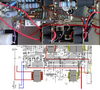
Just checked, all OK in that area, just looks odd.Found this - looks odd...