• You can now help support WorldwideDX when you shop on Amazon at no additional cost to you! Simply follow this Shop on Amazon link first and a portion of any purchase is sent to WorldwideDX to help with site costs.

New EFHW Homebrew for Local Operator

HomerBB

Sr. Member
Jan 4, 2009
3,933
2,633
273
68
Rogers, Ar
A friend called me up and asked me to build an EFHW for him like one I had done for another local OP a while back. A little horse trading later and he will have this antenna flying by tomorrow.

onehalf01a.jpg onehalf02a.jpg onehalf03a.jpg

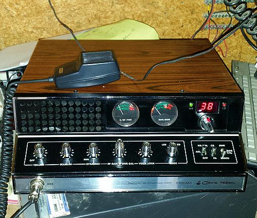
It may need a little fine tuning after it is in the air at his place. I had only enough time today to assemble it and fly it on my mast at 18' to the coax connector. Channel 1 showed a 1.1:1 SWR and channel 40 showed 1.1:1 in the shack.
My analyzer is on the blink so I am using my SWR meter to get it operational.
It showed to be a little long at 17' 4" when I dropped below the CB 40 for a check. Not too bad for off the bench and into the air.

I made easy contact 30+ miles out into SW Missouri as well as to some other locals with satisfactory performance.
 
  • Like
Reactions: 357magnum

Sure.
I will have to locate some stuff as I am operating from a couple of computers that are not the one I kept my files on. I'll give you all I can come up with.

First.
I used three 6' long aluminum tubes.
72"x5/8"
72"x3/4"
72"x7/8"
I inserted the 5/8" into the 3/4" to a depth of 4" as a start. I did the same with the end of the 3/4" into the 7/8" tubes. I have a 17' 4" vertical to start with.

The gray plastic box is an electrical 4"x4"x2" wall mount box. It is attached to the 7/8" tube with two ground rod clamps by the screw hole ears on the box.
I drilled a hole in the lower edge of the box in order to attach a SO239 coax connector there for the feed line.
Inside the box a put one of these matching networks I've used numerous times:

F6051.jpg

The matcher is connected to the vertical by way of a wire from the matcher in the box to the upper clamp that does double-duty attaching the matcher box.
This box with matcher is placed about 8" from the bottom of the vertical.
I pushed a hardwood dowel up into the bottom of the 7/8" lower tube 8" and then placed a 2'x 1" PVC tube over the dowel and the lower end of the vertical. I made the PVC tube fit snugly over all of this by wrapping tape around the 7/8" tube and the dowel. All of this was secured together with a self drilling screw through one upper side of the PVC.

If this isn't clear enough I'll snap a few detailed photos tomorrow before I deliver it to my friend.
 
Last edited:
How big is the capacitor ?
The over all length of the capacitor is not so important as the overlapping area. The capacitor is made of two 4.5" long 1/8" x 3/4" pieces of aluminum flat bar. I used double sticky sided adhesive gray colored tape as the insulator. I stuck the adhesive to one plate and left the red insulator on the other side so they would slide. Removing the red plastic insulator once I achieved a match resulted in a degradation of the match. I split the little piece of CPVC along its length to use as a tensioner to hold the plates together.
freehand schematic would be appreciated also!
I will try to do this, however, I am no artist by any means.
 
Homer, I recall a guy coming on to the forum sometime back and had an EFHW multi-band antenna...perhaps similar to your EF noted here. At least they look similar and I think he says his is a 1/2 wave.

Here is the link: http://www.worldwidedx.com/threads/thoughts-on-this-antenna.163202/page-1

I'm curious if you could check, if you have the frequency range, and see if your design will produce similar low SWR bandwidth functions near or on 10-14 meters...similar to what he showed us in a band width curve on page #3?
 
Last edited:
Hi Marconi. I no longer have the antenna. It went home with the OP I made it for.
I did not run a plot like that on it, I merely did a quick SWR tun for the CB band.

I don't know what was in the box on his antenna. I show the matcher type in these I make. I have seen recurrent highs and lows in the SWR plot like that before. The question that I would have is one of where the antenna is actually resonant. Without an accurate analyzer plot the SWR can undulate like that and the resonance only be in one of the low points, or even in a high point for that matter. I'd say just guessing that the antenna is only resonant where the physical length is right.

This one is of a length for the middle of the CB band. I will have to go back and tune it better when I get my analyzer recalibrated. At that point I will likely shorten it a little like I said above. It is at it's lowest SWR below channel 1.
 

dxChat
Help Users
  • No one is chatting at the moment.