
You are using an out of date browser. It may not display this or other websites correctly.
You should upgrade or use an alternative browser.
You should upgrade or use an alternative browser.
-
You can now help support WorldwideDX when you shop on Amazon at no additional cost to you! Simply follow this Shop on Amazon link first and a portion of any purchase is sent to WorldwideDX to help with site costs.
-
A Winner has been chosen for the 2026 July 4th Retevis RA89R Giveaway! Click Here to see who won!
Outdoor Loop
- Thread starter HomerBB
- Start date


B
BOOTY MONSTER
Guest
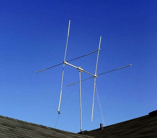
It is 5' 8" spacing.
This photo does not represent the completed project, only what I have now.
i really really really like that !!!!!!
any idea what it weighs ?
do you have a rotor yet ?
how did you decide on the spacing ?
are you gonna play with the spacing any to see how it changes ?
I live to pleasei really really really like that !!!!!!
Haven't weighed it, but very little by how it feels handling it.any idea what it weighs ?
I have an old TV rotatordo you have a rotor yet ?
I spread my arms as wide as they'd go . .how did you decide on the spacing ?
 Used a calculator
Maybe. I haven't gotten that far. Just making the parts.are you gonna play with the spacing any to see how it changes ?
How much
did the bandwidth change?
I will have to check it. Got it up but haven't been able to work with/on it, yet.
how did you tune the refelecter?
I simply added 5% to the driven length, then I double checked it with an online calculator and confirmed it to be close enough (within an in or so) to be trustworthy.
I considered tuning it with a beta match but decided to forgo that for now. Weather is closing in fast and still too much to get done around the house that takes my fun time away.
if you can find someone to help you do some tedius tuning have them go about 20 chanels lower then you want it to tune and throw a carrier for you to tune to. then point it to them and write down the reading then point it away and write it down. then cut about a 1/2 inch off and recheck. do this until you see it start to get weaker then you know you passed the point of tune but you wrote it all down so now you know what it should be so you can now go to the chanel you want it to tune on and set it to that exact reading by cutting off only a little bit more until its maxed out. you might be suprised at how much more performance it has in it if you tune it. i think i ended up with about a 3%-3.5% difference.
There in lies the trouble. Getting help on something like this from other CBers.
I can also use the MFJ-209 to find the right spot, I should think, no?
I can also use the MFJ-209 to find the right spot, I should think, no?
i cant imagine how the mfj can help max out the front to back but you can stick a mobile a few blocks away with a rubberband around the mic and set to ssb and set the carrier balance vr off a little to give a low level carrier but start 15 to 20 chanels below where you want your center chanel to be so you can pass it up while your recording the readings
If it was me doing this, I would have stuck to the beam calculator that I posted on this thread a few pages back. But it is your show and I am digging it all just the same.
The space between the reflector and the radiator can be maxxed for gain; but then the front-to-back will become worse and it will begin to act bi-directional once again.
I was reading today that when this beam's radiator is using an unbalanced feed it will skew the radiation pattern. When using a balanced feed to this beam's radiator it will make it uniform once again.
Sources:
The Ultimate Guide to 11 Meter CB Antennas
The Ultimate Guide to 11 Meter CB Antennas
"...The radiation pattern of the antenna on the left is a 4 element quad feed directly with coax. The radiation pattern of the antenna on the right shows a quad using a device (balun, gamma match etc.) to match the unbalanced coax feed to the balanced antenna. A clean pattern results..."
i cant imagine how the mfj can help max out the front to back but you can stick a mobile a few blocks away with a rubberband around the mic and set to ssb and set the carrier balance vr off a little to give a low level carrier but start 15 to 20 chanels below where you want your center chanel to be so you can pass it up while your recording the readings
I failed to realize you were speaking to F/B tuning, and so I was responding to you in terms of setting the reflector length. which, if you know the frequency your tuning to, simply add a feed wire to the reflector and adjust until you get it dead-on resonant at that frequency.
"...The radiation pattern of the antenna on the left is a 4 element quad feed directly with coax. The radiation pattern of the antenna on the right shows a quad using a device (balun, gamma match etc.) to match the unbalanced coax feed to the balanced antenna. A clean pattern results..."
Whether it will benefit to this end or not I don't yet know, but if you look at the photo again you'll notice there is a coax choke at the feedpoint of the driven.
If you mean a RF choke (aka 'ugly balun'), that isn't the same thing as getting a balanced feed. Your idea for a beta match is actually what I found online as one method to get the balanced effect. Then again, I'm not sure that using the RG-59 matching section is making it balanced as much as it is just an impedance match. I need to read more up on all of this BTW . . .
Quote:"...The Balun, simplifies hooking the coax to the driven element wire among other important things. The balun is secured to the spread arm with tie-wraps and outdoor electrical tape (I like 3M's). Notice here also, the area you should waterproof when you are done, by wrapping either electrical tape around it, or Radio Shacks coax seal..."

Quote:"...The Balun, simplifies hooking the coax to the driven element wire among other important things. The balun is secured to the spread arm with tie-wraps and outdoor electrical tape (I like 3M's). Notice here also, the area you should waterproof when you are done, by wrapping either electrical tape around it, or Radio Shacks coax seal..."
Last edited:
dxChat
- No one is chatting at the moment.