• You can now help support WorldwideDX when you shop on Amazon at no additional cost to you! Simply follow this Shop on Amazon link first and a portion of any purchase is sent to WorldwideDX to help with site costs.

Phantom amplifier 10 tube

Ronald Porter

Member
Apr 8, 2016
23
5
13
81
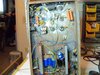
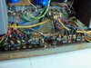
i was given this amp. there is a capacitor blown. Is there a schematic for this amp. It is not the triple stage amp. Must be older than that one. could be that the caps. were wired wrong on one side. the side that the one is gone. It looks like that was right. the positive comes from the end of the rectifier circuit. but it ticked when turned on and blew. does anyone happen to know this circuit. where the positive and negative wire up. here are some pictures off the circuit.thank you, Ron.
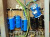
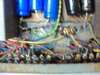
here are pictures of the diode section if you can see them clearly. the side that the cap. blew was the positive hook to the bottom where the 470kohm resistor is and where the wire from the diodes goes to. the negative end went to the top where the other cap is hooked. As soon as you turn it on that cap blew. I hooked it the same way as it was when I got it. the resistor is good, the diodes are good, so there must be something with the hook up. the other side must be alright nothing happened on that end, ?? Thank you
 

Attachments

  • 103_0516.JPG
    103_0516.JPG
    2.1 MB · Views: 211
  • 103_0517.JPG
    103_0517.JPG
    2.1 MB · Views: 217
  • 103_0518.JPG
    103_0518.JPG
    1.6 MB · Views: 193
  • 103_0519.JPG
    103_0519.JPG
    1.7 MB · Views: 184
Last edited:

Wow ! Blew is right ! ( first pic ) But one thing for sure IMHO , who ever was in there should have left it alone ! Their soldering skills are a bit " Lacking " Let alone what else they " Tried " to do ! :whistle::eek:o_O;)
 
OMG ! The sorrow in those pic's ! I had a 10 tube Phantom over 30 years ago , it didn't look that inside !?? The agony ! I know it wasn't you RP , but some people should stick to Land Scaping . Sorry .:whistle::censored::cry::eek::rolleyes: 73& God Bless , Leo
 
Okay, so this is a fairly-familiar problem. I call it the "Mix and (death) Match" problem.

The capacitors on the left all look identical. Good chance that their internal leakage resistance was the same in each of the three caps. This allows the 950 Volts DC to be divided equally three ways across each 350-Volt part.

This is a big deal. If one of the three gets more than a one-third share of the voltage, it will break down when that share exceeds the 350-Volt rating printed on it.

The right-hand three caps in series are a mix of parts from different sources. It appears the blue cap in that set of three received more than a one-third share and blew up.

When you use multiple electrolytic caps in series to obtain a higher voltage rating, you normally put a separate bleeder resistor across each capacitor. This serves to bleed off the stored charge safely when the power is removed, yes. But even more importantly it will divide the DC voltage equally. If all three resistors have the same value, of course.

The textbook name for this function is "equalizing" resistors.

D&A got away with leaving them out because they bought those parts in bulk. Three caps from the same factory carton would nearly always match just fine without those resistors. As a result, D&A left them out.

But when making a repair decades later, you can't count on this. We always install a separate 220k or 330k 2-Watt resistor across each filter cap in a series string like these. The exact resistance value is not critical, just so all of them are the same resistance value. It's cheap insurance. That strategy might well have prevented this breakdown.

Maybe.

But it's time to replace the three right-hand caps. You can't trust them after this happens. The three blue caps on the left are probably okay. But you should check the rectifier diodes to see if any of them have shorted internally from the overload. Just be sure to add those separate bleeder/equ resistors before you power it up again.

You don't have to use six resistors. You can tie the two series strings of three caps together, and get away with only three resistors, one across each parallel pair of caps. Takes two jumper wires.

73
 
Exactly.

That's the point of adding the ones they left out.

Or, you could roll the dice, leave them out this time and see if the same problem occurs again.

You might get away with leaving them out.

But whoever put in the last set of filter caps did NOT get away with it.

73
 
  • Like
Reactions: 357magnum
Thank you for all your help. I have the amp turning on with no problems. But there is no high voltage to the tubes, nothing,. I got to checking around and noticed that the standby -on high voltage switch is hooked to a bnc jack in the back input. does this amp have a separate power supply for the high voltage? because there is no voltage to the plates of the 6lq6 tubes. Strange, never seen on this old to have a separate supply. Thank you, Ron
 
The relay near the center of the chassis switches the high voltage to the plate circuits of the tubes, but only while it's keyed. No HV to the caps of the tubes on standby.

The "top" one of three filter caps in series has a wire to the rectifier bridge. You should have about 950 Volts DC there on standby.

If you don't this suggests the blown filter may have damaged the rectifiers.

If you DO have that high voltage at the filter caps on standby, watch that center relay when you key the radio. If the antenna relay clicks (the one between the coax socket) and the one near the center doesn't, the tubes won't get switched on.

The coil of the relay should measure between 9000 and 10000 ohms. If that coil is open, that would explain this problem.

73
I found the 980 volts with the switch on stand by. Hook the radio up and keyed it , the other set of relays keyed but the middle set did not key. the 980 volts was not on the tubes. so that relay must be bad. potter & brumfield ka-14dy relay. haven't been able to find it so far. still looking, thank you, Ron
 
Oddly enough, you'll find more than one type of 3PDT relays with 110 Volt DC coils.

Like here: https://www.rfparts.com/relays/relays-openframe.html

And this is where "DEE-CEE" really counts. A relay with a coil meant for 120 Volt *AC* is *NOT* suitable. The coil for the AC relays will overheat in this amplifier's DC circuit.

Check the coil of the old relay to see if you have about 9000 to 10,000 ohms resistance.

If you do, the problem with why it won't move when you key the mike may be with the antenna relay. The center contact of the relay between the coax sockets is what activates the HV relay. It's not that common for that center circuit of the antenna relay to go bad, but it's one of the possible causes.

And a burned-out coil in the HV relay does happen. There is 2-Watt resistor in series with the coil of the HV relay. If that resistor has lost its resistance value, this drives up the current in the coil of the HV relay. Makes the coil break down.

Naturally, replacing that resistor would prolong the life of a replacement relay.

73
I saw the relay on rf parts, have to order it. thank you. I getting 4.80kohms across the coil off the relay. there was a .05 z5u cap. on the relay, second pin down, hook to ground. it was burnt in half. don't know what did that?? Maybe to much input watts?? I'll keep you informed when I get the part installed and see what happens. I don't see anything else wrong. the tubes are all good. only one was dead (12at7a). the rest all 80 to 90%. thank you for the info. Ron
 

dxChat
Help Users
  • No one is chatting at the moment.
  • @ Wildcat27:
    Hello I have a old school 2950 receives great on all modes and transmits great on AM but no transmit on SSB. Does anyone have any idea?
  • @ ButtFuzz:
    Good evening from Sunny Salem! What’s shaking?
  • dxBot:
    63Sprint has left the room.