Thank you! I haven’t opened up the radio to turn down the wattage yet but I will be soon. I’m still going to put a low pass filter in line even if lowering the dk helps.Coax length shouldn't be an issue - sometimes a jumper cable that is too short between a radio and a amp can cause problems but that doesn't sound like it's the case for you.
The reason I suggested checking and swapping coax cable is because cheap coax can often fail or there can be bad connections with the connectors. People throw an old cable between the radio and amp and or amp and meter and get problems and think it's the amp when it's actually the coax.
Did you try turning down the deadkey and seeing if that had any effect?
I'd pick up a lowpass filter - more useful in the long run.

You are using an out of date browser. It may not display this or other websites correctly.
You should upgrade or use an alternative browser.
You should upgrade or use an alternative browser.
-
You can now help support WorldwideDX when you shop on Amazon at no additional cost to you! Simply follow this Shop on Amazon link first and a portion of any purchase is sent to WorldwideDX to help with site costs.
-
A Winner has been chosen for the 2026 July 4th Retevis RA89R Giveaway! Click Here to see who won!
Question for amp gurus
- Thread starter CherokeeSoccer
- Start date
Thank you for helping clear that up for me! I will let everyone know how it goes after I get the low pass filter I just ordered.The issue is harmonics. Frequencies above the channel frequency. A low-pass filter is all you need. The bandpass type single-band filters are for stations that have multiple radios operating different bands at the same time, like during the annual ARRL Field Day contest. All you need in this case is low-pass filtering.
73

That's an important question . Mine is 1.3 on DK then drops to 1.1 on modulation so I don't worry about it.Is the swr high with just a carrier? Or does the swr go up with modulation?
It’s high just with dk and I don’t see any change with modulation. I put a new Kenwood low pass filter inline both before and after the amp and it didn’t help.Is the swr high with just a carrier? Or does the swr go up with modulation?
I have seen input tune problems cause a high SWR on the output. If you put the SWR meter between the radio and amplifier, you will be able to see the amplifiers input match. Sometimes there is a variable capacitor on the input matching network inside the amp. If the amplifier has a fixed input capacitor, it can be replaced with a variable. A few pictures of the inside of the amplifier would let everyone see what you have. It is possible that something is out of place and someone might spot it. At the very least, we can figure out what the input network is.It’s high just with dk and I don’t see any change with modulation. I put a new Kenwood low pass filter inline both before and after the amp and it didn’t help.
Here is some work that i did to the input of my Texas Star 350.
Texas Star DX 350 HDV Input SWR | WorldwideDX Radio Forum
Last edited:
Thank you! I’m pretty new to all this but I’m learning thanks to the help of people like you. I will take the cover off and post some photos.I have seen input tune problems cause a high SWR on the output. If you put the SWR meter between the radio and amplifier, you will be able to see the amplifiers input match. Sometimes there is a variable capacitor on the input matching network inside the amp. If the amplifier has a fixed input capacitor, it can be replaced with a variable. A few pictures of the inside of the amplifier would let everyone see what you have. It is possible that something is out of place and someone might spot it. At the very least, we can figure out what the input network is.
Here is some work that i did to the input of my Texas Star 350.
Texas Star DX 350 HDV Input SWR | WorldwideDX Radio Forum
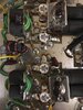
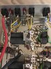
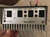
Here are some photos of the amp.I have seen input tune problems cause a high SWR on the output. If you put the SWR meter between the radio and amplifier, you will be able to see the amplifiers input match. Sometimes there is a variable capacitor on the input matching network inside the amp. If the amplifier has a fixed input capacitor, it can be replaced with a variable. A few pictures of the inside of the amplifier would let everyone see what you have. It is possible that something is out of place and someone might spot it. At the very least, we can figure out what the input network is.
Here is some work that i did to the input of my Texas Star 350.
Texas Star DX 350 HDV Input SWR | WorldwideDX Radio Forum
Attachments
A Gray. Looks like one of his, anyway.
Haven't seen one in a while. Seems to me it was more of a "finish it yourself" amplifier kit. Adding negative feedback kept it from oscillating. The input impedance was nowhere near 50 ohms.
I'll see if we have any notes on file for one like this.
73
Haven't seen one in a while. Seems to me it was more of a "finish it yourself" amplifier kit. Adding negative feedback kept it from oscillating. The input impedance was nowhere near 50 ohms.
I'll see if we have any notes on file for one like this.
73
If there is any way to solve the issues I’m willing to give it a try. I just don’t have the knowledge to know where to even begin. I’m decent with soldering but my experience with electronic circuitry is very limited. Any help would be greatly appreciated.A Gray. Looks like one of his, anyway.
Haven't seen one in a while. Seems to me it was more of a "finish it yourself" amplifier kit. Adding negative feedback kept it from oscillating. The input impedance was nowhere near 50 ohms.
I'll see if we have any notes on file for one like this.
73
As you can see in the photos this is a 4 transistor but I couldn’t find any adjustable capacitor in it either. I don’t know enough to properly adjust one anyway. lol I’ve been reading about negative feedback after Nomadradios reply but it’s way over my head. Is it possible to add a negative feedback circuit?I found the schematic for the Gray 2 transistor amp on cb tricks. It appears to have no input tuning capacitor at all.
The negative feed back could be a simple resistor from the output of each transistor to it's own input. How to figure out what value resistor is needed, I am not sure.As you can see in the photos this is a 4 transistor but I couldn’t find any adjustable capacitor in it either. I don’t know enough to properly adjust one anyway. lol I’ve been reading about negative feedback after Nomadradios reply but it’s way over my head. Is it possible to add a negative feedback circuit?
dxChat
- No one is chatting at the moment.