This is a "quick and dirty" class AB mod for the KL300p that I ran across some time ago. While this description is for the KL300p, this method of providing a small bias source can be applied to just about any class C amp. Basically any amp that grounds the bases of the transistors via an inductor is class C. In this case, the inductor is part of the input transformer.
Procedure: First I used a dremel tool to carve a notch all the way around the outside end (closest side to the switch assembly) of the input transformer, which is the smaller of the two transformers on the amp PCB. This disconnects the transformer from ground. Make very sure that you cut completely through the ground trace all the way around that end of the transformer. If you check for continuity with a DMM you'll get a reading of ~5 ohms. If you get a reading of 0 ohms, recheck to make sure that you've cut completely through the ground copper all the way around the end of the transformer.
I used a large 10W 100ohm resistor in line as well, one end of which I connected to the "Pre + Lin" side of the power switch which is on the topmost pin. When the switch is on, this pin is a source of 13.8V. This way, the bias is only supplied if the amp is on. This resistor limits the current that is supplied to the transistors, and it is connected in series with a large 3A silicon diode (1N5402), the side of which is physically touching the top of one of the SD1446s (there is thermal paste between the two) and the cathode end (stripe) is connected to ground right at the transistor on one of the emitter tabs. As you may already know a diode is simply a PN junction, and so this diode limits the bias voltage to the forward voltage drop of a silicon PN junction, generally .6-.7V depending on the junction temperature. At the connection point between the 10W resistor and the diode, I soldered one end of an RF choke (available from Radio Shack) which ensures RF cannot pass as we only want DC. The other end is connected to the brass tubes in the input transformer, on the same side as the cut that was made with the dremel. This replaces the ground connection that was there with the bias voltage. This completes the rudimentary bias supply. This small voltage applied to the bases (.6-.7V) is just right to keep the transistors turned "on" at all times, which means your amp is now class AB. Since the components used are fairly heavy-duty, the thick leads make for a nice stable structure so you don't have to worry about things moving around much.
This is a quick and dirty mod, partly due to limited room, and partly due to my feelings that simplicity is best for such an inexpensive amp.. however I see this same basic supply frequently in many 10-11m amps and even some Mirage VHF amps that are classified AB so by performing it you're getting very similar results to many major name manufacturer's amps and most other simple class AB amps.. In fact, since there is temperature tracking due to the physical arrangement of the diode and transistor you're actually a step ahead of many manufacturers.
There are much more complex bias designs out there that are meant to make sure the transistors are biased within precise parameters under all types of condition .. so if you really wanted to you could go much further with it and get even better results. This simple mod, combined with an effort to avoid overdriving the amp can help ensure that there is a reduction in the amount of distortion produced. If you think you're getting "crunchy" audio or fuzzy output then this mod might be just the thing you need.
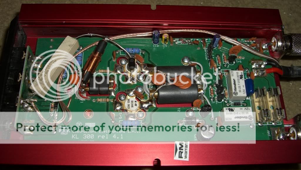
Here's a pic of the end result:
Anyway, I just thought folks here might like to have a good description and pic of this mod, since I know that many people are confused by bias and amp classes in general and how they are applied in real-world hardware.. this might help remove some of the confusion. Plus, if there are people out there with KL300p's that want cleaner SSB output and less distortion this will likely help them out too..
Procedure: First I used a dremel tool to carve a notch all the way around the outside end (closest side to the switch assembly) of the input transformer, which is the smaller of the two transformers on the amp PCB. This disconnects the transformer from ground. Make very sure that you cut completely through the ground trace all the way around that end of the transformer. If you check for continuity with a DMM you'll get a reading of ~5 ohms. If you get a reading of 0 ohms, recheck to make sure that you've cut completely through the ground copper all the way around the end of the transformer.
I used a large 10W 100ohm resistor in line as well, one end of which I connected to the "Pre + Lin" side of the power switch which is on the topmost pin. When the switch is on, this pin is a source of 13.8V. This way, the bias is only supplied if the amp is on. This resistor limits the current that is supplied to the transistors, and it is connected in series with a large 3A silicon diode (1N5402), the side of which is physically touching the top of one of the SD1446s (there is thermal paste between the two) and the cathode end (stripe) is connected to ground right at the transistor on one of the emitter tabs. As you may already know a diode is simply a PN junction, and so this diode limits the bias voltage to the forward voltage drop of a silicon PN junction, generally .6-.7V depending on the junction temperature. At the connection point between the 10W resistor and the diode, I soldered one end of an RF choke (available from Radio Shack) which ensures RF cannot pass as we only want DC. The other end is connected to the brass tubes in the input transformer, on the same side as the cut that was made with the dremel. This replaces the ground connection that was there with the bias voltage. This completes the rudimentary bias supply. This small voltage applied to the bases (.6-.7V) is just right to keep the transistors turned "on" at all times, which means your amp is now class AB. Since the components used are fairly heavy-duty, the thick leads make for a nice stable structure so you don't have to worry about things moving around much.
This is a quick and dirty mod, partly due to limited room, and partly due to my feelings that simplicity is best for such an inexpensive amp.. however I see this same basic supply frequently in many 10-11m amps and even some Mirage VHF amps that are classified AB so by performing it you're getting very similar results to many major name manufacturer's amps and most other simple class AB amps.. In fact, since there is temperature tracking due to the physical arrangement of the diode and transistor you're actually a step ahead of many manufacturers.
There are much more complex bias designs out there that are meant to make sure the transistors are biased within precise parameters under all types of condition .. so if you really wanted to you could go much further with it and get even better results. This simple mod, combined with an effort to avoid overdriving the amp can help ensure that there is a reduction in the amount of distortion produced. If you think you're getting "crunchy" audio or fuzzy output then this mod might be just the thing you need.
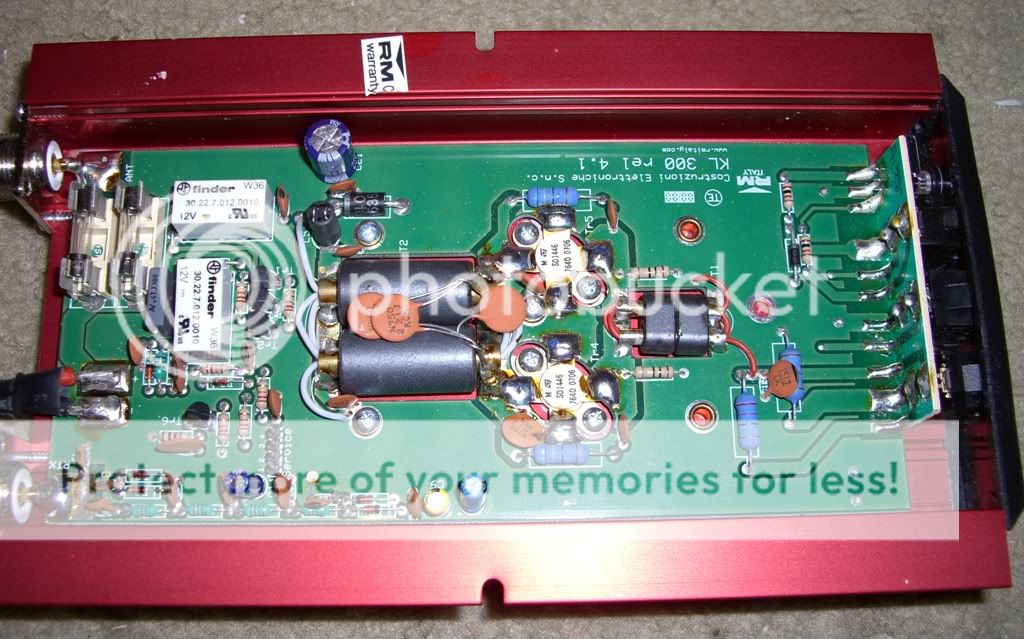
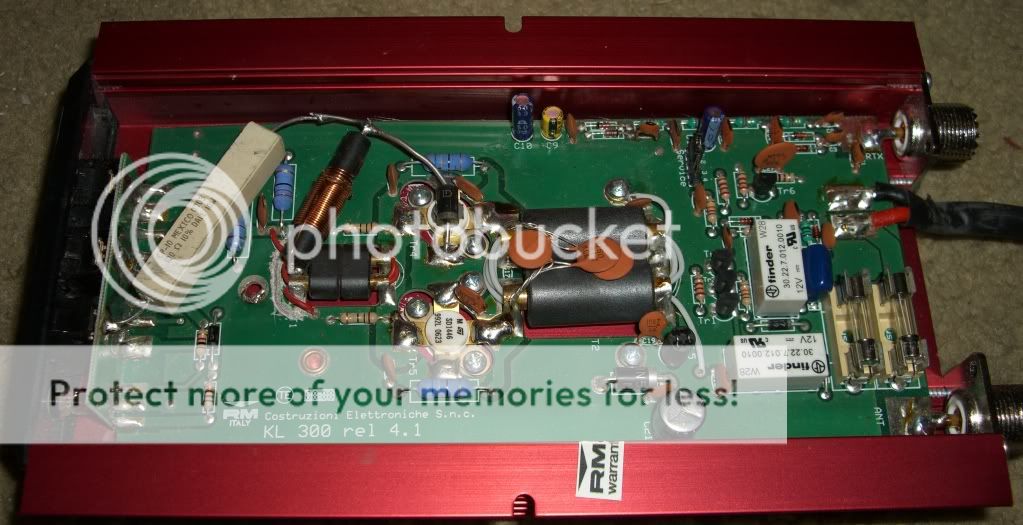
Here's a pic of the end result:
Anyway, I just thought folks here might like to have a good description and pic of this mod, since I know that many people are confused by bias and amp classes in general and how they are applied in real-world hardware.. this might help remove some of the confusion. Plus, if there are people out there with KL300p's that want cleaner SSB output and less distortion this will likely help them out too..
Last edited: